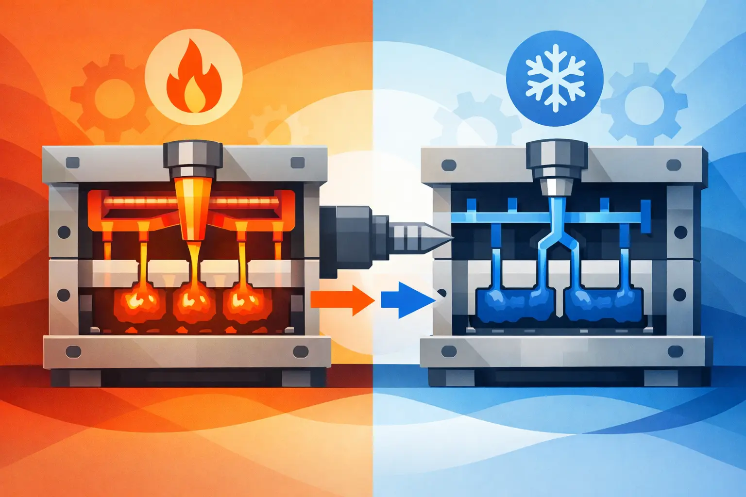
A moulded assembly can look simple on a screen and still become expensive, slow, and unstable in production. That gap is where design for moulded assemblies matters most. If the assembly is not engineered for moulding, handling, fit-up, and repeat production at the same time, problems show up fast – warped parts, inconsistent snap fits, long cycle times, high scrap, and tooling changes that should have been avoided.
For product developers, OEMs, and procurement teams, this is rarely a single-part problem. It is an interaction problem. One housing half may mould well on its own, but fail when paired with a cover, seal, insert, or fastener. A clip may work in prototype quantities, then crack after repeated production because material flow, gate location, and wall transitions were never aligned with actual use. Good assembly performance starts much earlier than final inspection. It starts at design.
What design for moulded assemblies really means
Design for moulded assemblies is the discipline of developing plastic parts as a production system rather than as isolated components. The goal is to make every feature work in three environments at once: in the mould, on the assembly line, and in the finished product.
That sounds straightforward, but trade-offs are built into every decision. A thicker wall may improve stiffness while increasing sink risk. A tighter fit may improve feel while reducing tolerance forgiveness. A moulded-in fastener boss may remove a secondary operation while creating weld line or stress issues if resin selection and gate strategy are wrong. The right answer depends on the application, the expected volume, the material, and the assembly method.
This is why moulded assemblies should be reviewed as complete production units. Parting lines, ejection, draft, shrinkage, joining method, and post-mould handling all affect whether the design will scale cleanly.
The biggest failures start with part interaction
Many assembly issues are created by reasonable decisions made one part at a time. A designer may optimise each component for geometry and appearance, but still create stack-up problems once those parts meet. That is common in enclosures, meter components, covers, brackets, automotive trim pieces, and utility products where multiple moulded parts must align with repeatable force and position.
Tolerance accumulation is usually the first warning sign. If several dimensions each vary within acceptable limits, the final assembly can still miss its functional target. Holes shift, latch features misalign, sealing surfaces lose compression, and visible gaps become inconsistent. In plastic assemblies, this risk increases because parts move with temperature, moisture, shrink variation, and fibre orientation.
The fix is not simply tighter tolerances. Tighter tolerances often raise tooling cost and process sensitivity without solving the root issue. A better approach is to design datum strategy, locating features, and assembly interfaces that control the dimensions that matter most while allowing noncritical variation where the process naturally needs it.
Fit features need process logic
Snap fits, bosses, ribs, slots, and alignment pins should not be treated as purely geometric features. They are process features. Their performance depends on resin behaviour, wall balance, mould filling, and cooling consistency.
A snap arm with sharp transitions may pass basic CAD review but fail after moulding because stress concentrates at the base. A boss placed in a thick wall region may create a sink that changes mating performance. A rib added for strength may distort a cosmetic surface or interfere with flatness needed for a gasket. These are not separate concerns. In moulded assemblies, they are the same concern viewed from different stages of production.
Material choice changes the assembly strategy
Material selection is often discussed in terms of strength, impact, heat, or chemical resistance. For moulded assemblies, those properties are only part of the picture. The resin also affects shrinkage behaviour, dimensional repeatability, weld line strength, friction, creep, and how features survive assembly loads over time.
For example, a glass-filled grade may improve stiffness and dimensional stability in one direction while increasing anisotropic shrinkage and wear on tooling. An unfilled material may offer better snap fit fatigue performance but create more movement under load. A part used in an electrical enclosure may need flame performance, but that same resin choice can affect flow length and gate requirements.
This is where early coordination pays off. Material, geometry, and tool design should be developed together. If they are handled in sequence, the assembly usually inherits compromises that could have been avoided.
Tooling decisions shape assembly quality
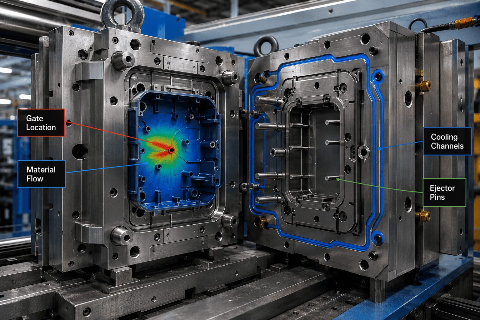
A moulded assembly is only as repeatable as the tool that makes it. Gate location, runner balance, venting, cooling layout, and ejection strategy all influence whether mating features come out stable enough for reliable assembly.
Consider a housing with precision alignment posts and a visible exterior. If the gate is placed for easy fill but creates differential shrink across the sealing plane, the two halves may never seat consistently. If cooling is uneven, the part may twist just enough to create rework during fastening. If ejector placement marks a functional surface, downstream operators are left solving a tooling problem manually.
Good design for moulded assemblies accounts for these realities before the tool is cut. In practice, that means reviewing where functional dimensions sit relative to flow direction, where weld lines land, how critical surfaces cool, and how the part will be removed from the mould without stressing thin or delicate features.
Assembly method should be chosen early
Screws, snap fits, ultrasonic welding, heat staking, inserts, and adhesive bonding each create different design rules. Problems start when the joining method is selected late and forced onto a part that was designed for something else.
Screw assembly may seem forgiving, but it brings boss design, torque limits, crack resistance, and cycle time into play. Snap fits reduce hardware count but demand careful strain control and tolerance planning. Ultrasonic welding can produce clean, repeatable joints, yet it requires proper energy director geometry, part support, and material compatibility.
There is no universal best method. The right choice depends on service conditions, assembly speed, disassembly needs, cosmetic requirements, and total production cost.
Designing for production means designing for variation
Prototype success can hide production weakness. Hand-built samples are often assembled more carefully, under less time pressure, and from a narrower material and process window than full production. That is why some designs pass validation and then struggle once volume begins.
A production-ready assembly is tolerant of normal variation. It does not depend on perfect operator technique. It does not need forceful correction at fit-up. It does not ask a mould to hold cosmetic, structural, and precision alignment requirements in the same uncontrolled area.
This is where practical engineering discipline matters most. Critical dimensions should be tied to realistic process capability. Features should guide assembly naturally. Components should be designed for orientation, handling, and fixture support if secondary operations are required. If the part needs printing, plating, insert loading, or packing protection, those steps should be anticipated in the geometry.
At Glasfil, this is exactly why in-house control matters. When mould design, mould modification, moulding, secondary processes, and quality checks are aligned under one operation, assembly issues can be solved at the source instead of being passed between suppliers.
What experienced teams review before release
Before a moulded assembly goes to tooling, several questions should already have clear answers. Which dimensions truly control function? Where will the material shrink unevenly? How will the parts locate during assembly? What happens if the material lot, temperature, or cycle changes slightly? Where are the likely cosmetic risks? Can maintenance or tool modification be done without redesigning the entire assembly?
These questions sound basic, but they separate a part that can be moulded from an assembly that can be manufactured reliably. The best projects resolve them early, when changing geometry is fast and inexpensive.
This is also why assembly design should involve toolmakers and production engineers, not only product design. CAD can confirm intent. Production experience confirms whether that intent will repeat across thousands or millions of cycles.
Design for moulded assemblies is really design for speed
Most delays in plastic part programs are not caused by one major failure. They come from accumulated corrections – boss adjustments, latch changes, gate moves, steel-safe edits, warpage fixes, fixture updates, and inspection revisions. Each one adds time, cost, and uncertainty.
Design for moulded assemblies reduces that correction loop. It connects product intent with tooling logic and production reality before launch. That shortens time to approval, improves first-pass yield, and gives procurement teams fewer surprises after the purchase order is issued.
For companies trying to launch new products or stabilise an existing one, that matters more than a clean prototype. What matters is whether the assembly can run repeatedly, meet fit and function, and move through production without constant intervention.
The strongest moulded assemblies are not the most complicated. They are the ones designed with enough discipline to make moulding, joining, and use all work together from the start. That is where cost comes down, quality goes up, and schedules stop slipping.
Contact us today to discuss your project requirements or request a quotation. Let’s build a production process you can depend on.