 A mould that looks fine in CAD can still fail on the press floor. Parts warp, gates blush, cycle time stretches, and what seemed like a small tooling shortcut turns into weeks of correction work. That is why knowing how to design a plastic injection mould is not just a tooling exercise. It is a production decision that affects quality, cost, lead time, and how reliably a part can scale.
For OEMs, product developers, and procurement teams, the real question is not whether a mould can be built. It is whether the mould will run consistently, hit the target cycle, and hold dimensions over repeat production. Good mould design starts long before steel is cut, and it only works when part design, material behaviour, machine capability, and manufacturing goals are aligned from the start.
How to design a plastic injection mould starts with the part
The mould should never be designed in isolation. The part geometry defines almost every major tooling decision, including parting line location, gate style, ejection method, core and cavity layout, and cooling strategy. If the part has thick-to-thin transitions, deep ribs, cosmetic surfaces, undercuts, or tight tolerances, those details need to be reviewed before mould architecture is locked in.
Wall thickness is usually the first place to look. Uniform walls promote balanced filling, more predictable shrinkage, and shorter cooling times. When walls vary too much, the mould has to compensate for a part design problem that may never fully go away. Sink marks, voids, and warpage are often traced back to geometry choices that should have been corrected before tooling began.
Draft is another common issue. A part may be technically moldable with minimal draft, but that does not mean it will eject cleanly at production speed. Textured surfaces, deep features, and high-gloss cosmetic areas all change the draft requirement. The trade-off is simple: adding draft can affect form and fit, but not adding enough draft can damage parts and slow the process.
Build the mould around material behaviour
Resin selection changes mould design more than many buyers expect. A filled nylon does not behave like polypropylene. ABS does not shrink like acetal. Materials differ in flow length, shrink rate, abrasive wear, processing temperature, and sensitivity to moisture. Those differences affect gate size, venting, steel selection, cooling layout, and expected maintenance intervals.
If the selected material has glass fibre or mineral filler, wear resistance matters. Gates and runners may erode faster, and shut-off areas need closer attention. If the resin is heat-sensitive, shear at the gate becomes more critical. If shrinkage is high or anisotropic, cavity dimensions and cooling balance become more difficult to control.
This is why mould design should be tied to the actual production resin, not a placeholder. Designing around an assumed material and changing it later often creates avoidable rework. In a production environment, that delay costs more than the upfront engineering time required to validate the correct resin early.
Choose the right mould layout for volume and part complexity
A simple single-cavity tool and a high-output multi-cavity mould solve very different business problems. The right choice depends on annual volume, required cycle time, part size, machine capacity, and budget. There is no universal best option.
For lower-volume or highly engineered parts, a single-cavity mould can offer tighter process control and easier adjustments during launch. For stable, repeatable parts with higher demand, multi-cavity tools can reduce piece price and increase output. Family moulds can look attractive when multiple components are needed together, but they also create balancing challenges if part volumes or fill behaviour differ.
Parting line strategy matters at this stage as well. A clean parting line can simplify machining, improve venting access, and reduce flash risk. But the best parting line is not always the most visually hidden one. Sometimes, the practical production choice is to place it where steel conditions are stronger and ejection is more reliable.
Gate and runner design decide how the mould fills
If filling is inconsistent, the rest of the mould design is already working from a weak foundation. Gate location controls flow pattern, weld line placement, packing efficiency, and cosmetic appearance. A gate should support complete fill and stable packing while minimising visible defects and post-processing problems.
The best gate location is usually the one that fills the part evenly and packs its critical dimensions first. That may not be the location that is easiest to machine or least visible after moulding. This is one of the most common trade-offs in tooling.
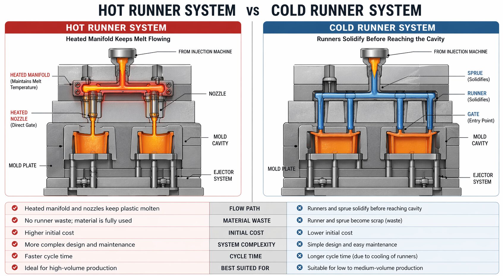
Runner design follows the same logic. Cold runner systems are often cost-effective and easier to maintain, especially for simpler parts or materials that run well with conventional layouts. Hot runners can reduce scrap, improve automation, and support faster cycle times, but they increase tooling cost and add thermal control complexity. For some programs, the savings justify the investment. For others, a well-designed cold runner is the smarter production decision.
Cooling design determines cycle time and dimensional stability
Many mould problems are cooling problems in disguise. If the tool does not remove heat evenly, parts will warp, dimensions will drift, and cycle times will grow. Cooling is not a secondary detail. It is one of the main drivers of productivity.
A strong cooling layout places channels close enough to the moulding surface to control heat without weakening the steel. The spacing needs to suit the part geometry, material, and expected cycle demands. Areas with heavy mass, such as bosses or thick sections, often need extra attention because they hold heat longer than nominal walls.
Balanced cooling is just as important as aggressive cooling. A tool that cools one side of the part much faster than the other can create internal stress and distortion even when the total cycle time looks acceptable. For tight-tolerance parts, cooling circuit design should be treated as a precision engineering task, not a standard template.
Venting, ejection, and shut-offs are where reliability is won or lost
Air has to leave the cavity as the melt enters. If venting is poor, the mould may burn material, short shot in hard-to-fill areas, or require excessive injection pressure. Vents need to be placed where air naturally traps, especially near end-of-fill locations, ribs, and deep features. Proper vent depth depends on the resin, because too shallow will not vent and too deep can flash.
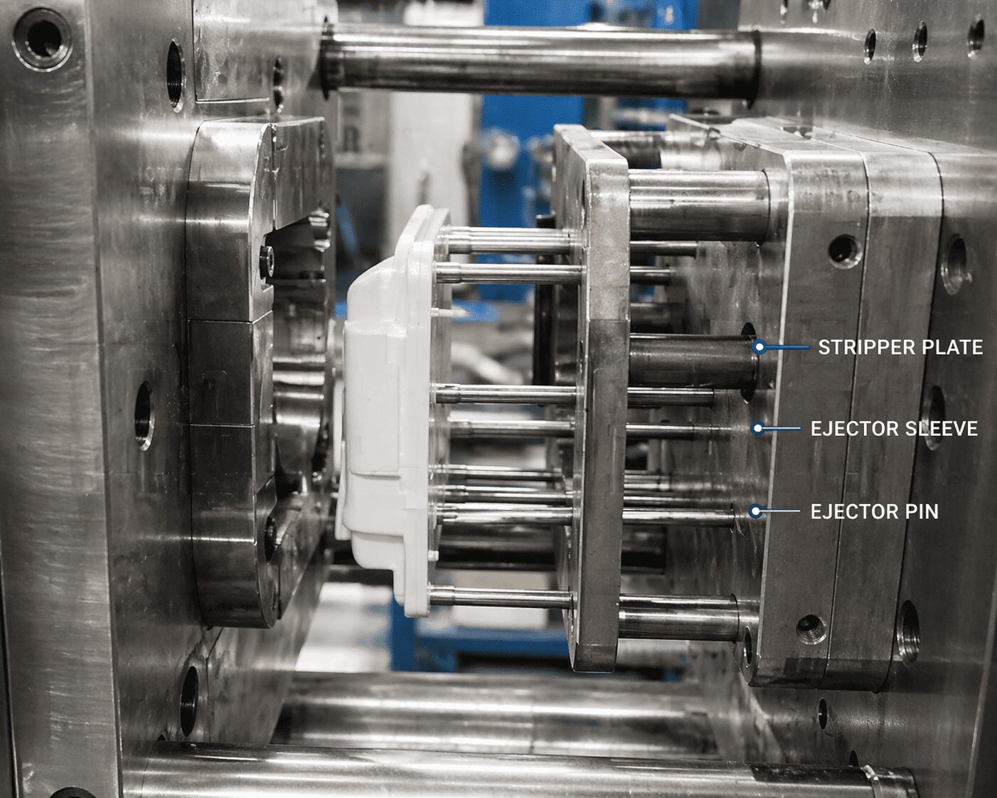
Ejection deserves the same level of attention. Pins, sleeves, stripper plates, or lifters must push the part off the core without creating witness marks, distortion, or sticking. The ejection method should match the part shape and surface requirements. A part with fragile ribs or cosmetic faces cannot be treated like a purely functional component.
Shut-offs and side actions also need careful design. Undercuts may require slides, lifters, or collapsible cores, but every added mechanism increases cost, maintenance, and timing complexity. Sometimes, redesigning the part is the better move. Sometimes the geometry cannot change, and the mould must absorb that complexity. Good tooling decisions come from understanding which cost is lower over the full program life.
Use mould flow and DFM review before steel is cut
Simulation is not a replacement for tooling experience, but it is a useful filter. Mould flow analysis can highlight pressure concerns, weld line locations, air traps, and potential imbalance before the design is finalised. It is especially valuable for technical parts, thin walls, multi-cavity layouts, and filled materials.
A proper design-for-manufacturing review should challenge the part and the mould together. Can the tolerances actually be held in production resin? Is the surface finish realistic for the geometry? Will the gate vestige be acceptable? Does the expected machine tonnage align with the tool design? These are not small details. They decide whether the first sampling moves efficiently or turns into repeated modification work.
In a fully integrated operation, design, tooling, moulding, and quality teams should review these points together. That shortens the gap between design intent and production reality, and it reduces the handoff errors that often appear when tooling and moulding are split across different suppliers.
How to design a plastic injection mould for long-term production
A mould is not just built for first shots. It is built for maintenance cycles, repeat orders, process stability, and future engineering changes. That means steel selection, wear areas, replaceable inserts, and service access all matter. A mould that runs well for a trial but is difficult to repair or modify can become expensive very quickly.
For programs with expected design revisions, modular inserts can reduce future downtime. For high-volume tools, wear components should be easy to replace. For parts with cosmetic or sealing requirements, quality checkpoints should be built into both tooling validation and production startup.
This is where in-house control makes a measurable difference. When the same manufacturing partner handles mould design, fabrication, modification, sampling, and production, feedback loops are shorter, and corrections move faster. At Glasfil, that integrated approach helps turn engineering decisions into production-ready tooling on a tighter timeline and with better process visibility.
The best mould design is not the one with the most features or the lowest quoted tooling price. It is the one that fits the part, the resin, the volume, and the production plan without forcing constant correction later. If you approach mould design with that standard, you do not just get a tool. You get a manufacturing asset that keeps working when deadlines tighten and volumes rise.
Ready to move from design to production with confidence?
At Glasfil, we work closely with OEMs, product developers, and procurement teams to turn part designs into production-ready moulds that run reliably and efficiently. From early DFM review to tooling, sampling, and full-scale manufacturing, our integrated approach helps reduce risk, shorten lead times, and improve consistency.
Contact us today to discuss your project requirements or request a consultation. Let’s make sure your next mould is built to perform — not just to run.