 If you are sourcing a custom plastic part, knowing how a plastic injection moulding machine works helps you ask better questions before steel is cut. Machine size, shot capacity, clamp force, melt control, and cooling efficiency all affect part quality, lead time, and unit cost. For OEMs, engineers, and procurement teams, this is not background theory. It is production risk control.
How a plastic injection moulding machine works in real production
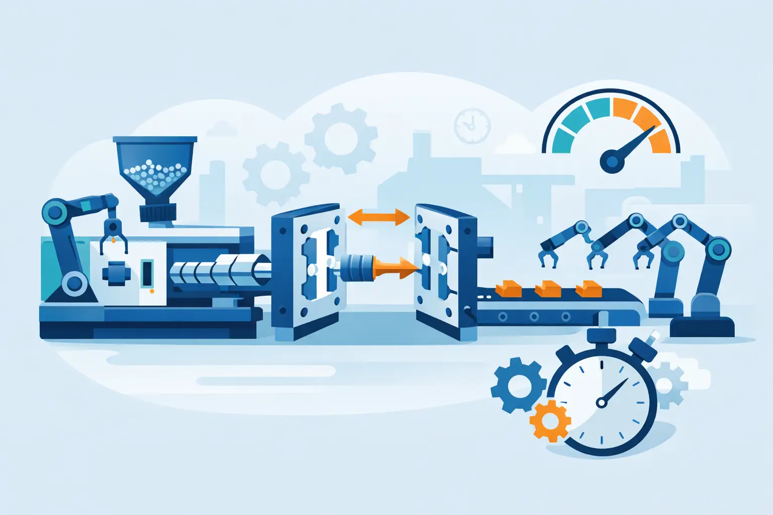
At a basic level, the machine takes plastic resin, melts it, pushes that melt into a closed mould under pressure, cools it until it holds shape, and ejects the finished part. That sounds simple. In production, each stage has variables that determine whether parts come out dimensionally stable and repeatable over thousands or millions of cycles.
A plastic injection moulding machine is built around two main systems – the injection unit and the clamping unit. The injection unit handles material feeding, melting, dosing, and injection. The clamping unit closes the mould, holds it shut against cavity pressure, opens it after cooling, and supports part ejection. Around these two systems is the control platform that manages temperature, pressure, speed, timing, and sequence.
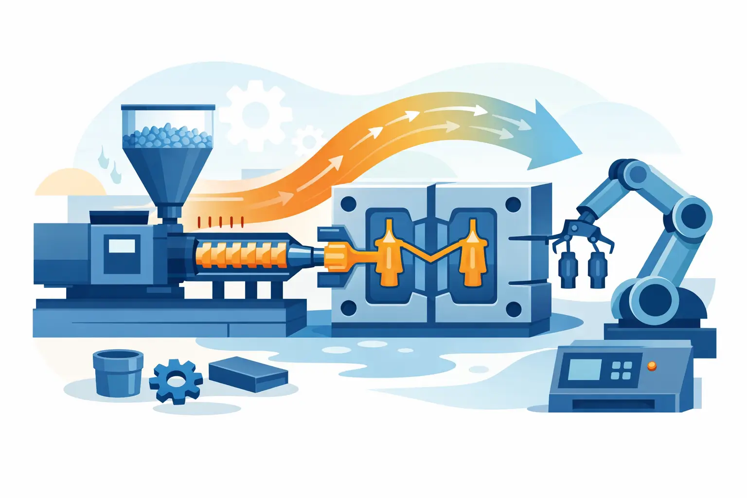
The process begins with resin, usually in pellet form, loaded into a hopper. From there, the pellets fall into a heated barrel. Inside the barrel, a rotating screw moves the material forward. The screw does more than transport plastic. It compresses, mixes, and plasticises the resin as heater bands and shear heat bring it to the required melt condition.
That melt condition matters. If the material is too cold, flow resistance goes up, short shots become more likely, and weld lines may weaken the part. If it is too hot, the polymer can degrade, causing discolouration, odour, brittleness, or dimensional drift. Different resins behave differently, which is why machine setup always depends on part geometry, wall thickness, tool design, and material grade.
The five stages of the moulding cycle
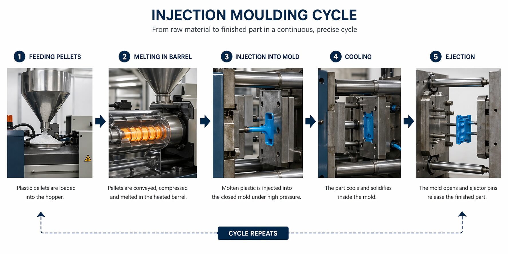
1. Feeding and plasticising
Resin enters the barrel through the feed throat and moves along the screw flights. As the screw rotates, the channel depth becomes smaller, which compresses the pellets and helps them melt evenly. Additives, colourants, or regrind may also be blended at this stage, depending on the application and quality requirements.
During screw rotation, molten plastic collects in front of the screw tip. This creates the shot size needed for the next cycle. The screw gradually retracts as material accumulates, preparing a controlled volume of melt for injection.
2. Mould closing and clamping
Before injection starts, the mould halves must close fully, and the machine must build enough clamp force to resist injection pressure. If the clamp force is too low, the mould can part slightly during filling and create flash. If the clamp force is too high, it can put unnecessary stress on the tool and machine while increasing energy use.
Clamp force is usually discussed in tons. Bigger does not automatically mean better. The correct machine tonnage depends on projected part area, material behaviour, cavity count, and process pressure. An oversized machine can be inefficient. An undersized one creates instability.
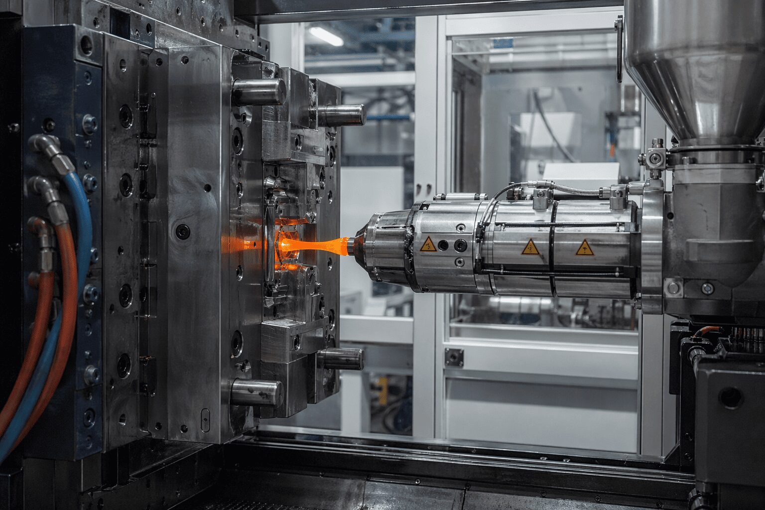
3. Injection and filling
Once the mold is closed, the screw moves forward like a plunger and injects molten plastic through the nozzle, sprue, runner system, and gate into the cavity. This stage happens quickly, often in a fraction of the total cycle time, because the goal is to fill the cavity before the melt front cools too much.
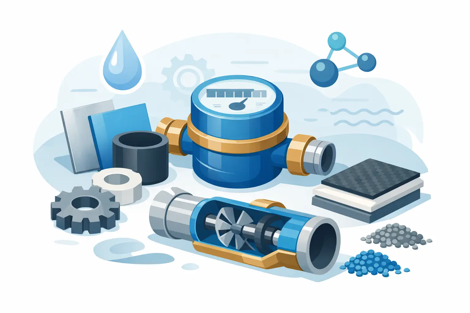
Injection speed affects surface finish, knit line strength, and air entrapment. Pressure affects how completely the cavity fills, especially in thin-wall or complex parts. The right filling profile depends on the tool and the part. A cosmetic housing, a structural clip, and a water meter component will not run with the same settings.
4. Packing, holding, and cooling
The cavity may look full at the end of the injection, but the cycle is not finished. As plastic cools, it shrinks. Packing pressure, also called holding pressure, pushes additional material into the cavity to compensate for that shrinkage before the gate freezes.
This stage has a direct effect on sink marks, voids, weight consistency, and final dimensions. Too little packing can leave underfilled areas or internal weakness. Too much can overpack the part, increase stress, and make ejection harder.
Cooling usually takes the largest share of cycle time. The mould contains cooling channels that remove heat from the plastic until the part is rigid enough to eject. Cooling design is one of the biggest drivers of productivity. A well-designed mould can reduce cycle time significantly while improving dimensional control. A poor cooling layout creates hot spots, warpage, and avoidable delays.
5. Mould opening and ejection
After the required cooling time, the clamp opens the mould, and the ejection system pushes the part out. Depending on the tool, this may involve ejector pins, sleeves, stripper plates, air assist, or robotic handling.
Ejection must be controlled carefully. If the part is still too hot, it can deform. If the ejection force is uneven, the surface can be marked, or thin sections can crack. This is especially relevant for tight-tolerance parts or parts that move directly into secondary processing, such as trimming, printing, assembly, or packing.
What each machine component actually does
The hopper stores and feeds raw material. In some cases, drying equipment is connected because moisture-sensitive resins such as nylon or polycarbonate must be conditioned before moulding. Moisture left in the material can create splay, bubbles, and weak mechanical performance.
The barrel and screw are the centre of melt preparation. Screw design affects mixing quality, output stability, and shear level. Not every screw is ideal for every resin. Commodity materials, filled engineering polymers, and flame-retardant grades can require different screw geometries and process windows.
The nozzle transfers the melt from the barrel to the mould. It must maintain temperature without drooling or freezing off. The mould is the precision tool that shapes the part, but it also controls venting, cooling, surface finish, gate behaviour, and ejection. That is why tooling quality has such a large impact on final production performance.
The clamping unit closes and holds the mould under load. The machine controller coordinates the cycle and records process data. On modern equipment, this data is essential for repeatability, troubleshooting, and process validation.
Why the process is never just about the machine
Buyers sometimes ask for machine tonnage first, as if the press alone determines capability. It does not. A strong result comes from the interaction between material, tool design, machine performance, and process control.
For example, a thin-wall electronics part may need high injection speed and precise venting more than an extreme clamp size. A glass-filled structural component may depend heavily on screw recovery control, mould steel choice, and cooling balance. A cosmetic consumer part may rise or fall on gate placement and texture replication. The machine matters, but only within the full manufacturing system.
This is why in-house control across mould design, tooling, moulding, modification, and quality assurance can reduce delays. If a part sticks in the tool, flashes at the parting line, or shows sink in a ribbed section, the fastest fix often involves both tooling and processing. When those capabilities are split across suppliers, every adjustment takes longer.
Common defects and what they usually point to
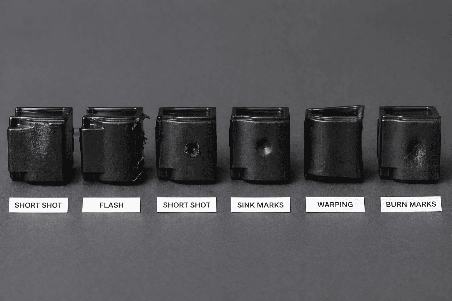 Understanding how a plastic injection moulding machine works also helps explain why defects appear. Short shots often point to insufficient fill, restricted flow, trapped gas, or low melt temperature. Flash usually signals excessive cavity pressure, poor shutoff, or insufficient clamp support. Sink marks often trace back to thick sections, poor packing, or uneven cooling.
Warping is more complicated. It can come from unbalanced cooling, part geometry, fibre orientation, or stress locked into the part during filling and packing. Burn marks often indicate trapped air or over-compression at the flow front. Surface defects may involve mould finish, contamination, moisture, or unstable process conditions.
There is rarely a single universal fix. That is why experienced moulders treat troubleshooting as a controlled engineering exercise, not trial and error.
What buyers should ask before approving production
If you are evaluating a manufacturing partner, the better question is not just whether they have injection moulding machines. Ask how they match machine capacity to part and tool requirements, how they validate process windows, how quickly they can modify moulds if needed, and how they control repeatability over long production runs.
Also ask about material handling, quality checks, secondary operations, and lead time from design approval to production. These details affect the total project outcome far more than a simple machine count. A supplier with integrated tooling, moulding, finishing, packing, and shipping can usually react faster when product changes or volume shifts occur.
At Glasfil, this is where the process becomes practical. The machine is one part of the system. The real value comes from aligning tooling, process control, and production planning so the part runs correctly, repeatedly, and on schedule.
When you understand the machine, you make better sourcing decisions. And when your supplier understands the full process around it, you get parts that perform the same way on the first run and the fifty-thousandth.
If you are sourcing a custom plastic part, don’t leave performance and cost to chance. Work with a team that understands not just the machine, but the full production system behind it.
Contact us today to request a consultation or quotation, and let us help you bring your part into stable, scalable production.