A part can look perfect in CAD and still fail on the shop floor. That usually happens when the plastic part design guide is treated as a checklist instead of a production decision tool. In injection moulding, small geometry choices affect tooling complexity, cycle time, cosmetic quality, and long-term repeatability.
For product developers, procurement teams, and OEMs, that matters early. A wall that is too thick can create a sink and long cooling times. A rib that is too aggressive can print through to the show surface. An undercut that seems minor in design review can add side actions, maintenance, and cost for the life of the program. Good part design is not just about making the shape possible. It is about making the part stable, scalable, and economical at production volume.
What a plastic part design guide should actually do
A useful plastic part design guide should help teams balance function, manufacturability, cost, and speed to launch. Those goals do not always align. The strongest geometry for a load-bearing feature may not be the easiest to fill. The cosmetic standard a brand wants may require tighter material and tooling control than the original budget assumed.
That is why experienced manufacturers review parts through a production lens, not just a design lens. Material flow, gate location, ejection, shrinkage, weld lines, venting, and dimensional variation all need to be considered before steel is cut. Fixing these issues in the design stage is far faster and less expensive than modifying a mold after first trials.
Start with material and process, not just shape
Part geometry should be developed around the selected resin and the intended moulding process. Too many projects do this backwards. The team designs the part first, then tries to force the material to behave inside that geometry.
Different resins shrink differently, tolerate wall transitions differently, and respond differently to heat and pressure. A polypropylene housing, a glass-filled nylon structural component, and a cosmetic ABS cover do not follow the same design rules in practice. The acceptable draft, expected warpage behaviour, gate sensitivity, and surface finish performance can change significantly from one material family to another.
If the part has demanding mechanical or environmental requirements, the material decision should happen early. Exposure to heat, moisture, UV, chemicals, or impact loading can narrow the options fast. Once the resin is realistic, geometry can be refined to support stable moulding rather than idealised shapes.
Wall thickness controls more than strength
When engineers think about wall thickness, they often think about durability. In moulding, thickness also controls fill behaviour, cooling time, shrinkage, and visual quality. Uniform walls usually perform better than large thickness swings because the part cools more evenly.
Thick sections are a common source of sink marks and internal stress. They also extend cycle time, which directly affects part cost at volume. If strength is needed, adding localised reinforcement through ribs or gussets is often better than simply making the entire part thicker.
That said, extremely thin walls are not automatically better. Thin sections can be difficult to fill, especially over long flow lengths or in heavily featured parts. The right answer depends on material viscosity, part size, gate strategy, and machine capability. Production-focused design means choosing a wall strategy that the mould can repeat reliably.
Ribs and bosses need restraint
Ribs are useful because they improve stiffness without adding the mass and cooling penalty of thick walls. Butthe rib design has to be controlled. If ribs are too thick relative to the nominal wall, they often create read-through or sink on the opposite surface. That is a cosmetic issue on visible parts and a quality issue on precision components.
Bosses create similar challenges. They are essential for screws, inserts, and assembly points, but unsupported bosses can become stress concentrators or moulding defects. Connecting bosses with gussets and maintaining proper wall relationships usually improves performance.
This is where design intent and production reality need to meet. A fastening feature that works in a prototype may crack in repeated assembly, distort during cooling, or create steel conditions that are difficult to maintain. The best feature is not the one that only works once. It is the one that survives production, assembly, and field use.
Draft is not optional
Parts need a draft so they release cleanly from the mould. Without enough draft, ejection force rises, surfaces scuff, dimensions become inconsistent, and tool wear increases. These problems are especially common when textured surfaces or deep walls are involved.
Many delays start with a simple issue: the part was designed with vertical walls because they looked cleaner in CAD. In production, those walls become a risk. Draft should be built into the design from the beginning, and it should reflect the actual surface finish required. Textured tools generally need more draft than polished ones.
There is sometimes pushback because a draft can affect fit or appearance. That is a fair concern. But the trade-off should be managed deliberately. If one area truly cannot accept the standard draft, the tooling approach, shutoff design, and maintenance implications need to be understood before launch.
Corners, transitions, and stress behaviour
Sharp internal corners look precise on screen, but they rarely help a moulded part. They restrict flow, concentrate stress, and can complicate tool fabrication. Radii improve both material movement and part durability.
Transitions matter just as much. Abrupt changes from thick to thin sections often create hesitation, differential shrinkage, and cosmetic variation. More gradual changes usually mould better and produce more stable dimensions. On structural parts, they also reduce stress concentration.
These details may sound small, but they influence whether a part runs cleanly at scale. In high-volume programs, repeatability is where profit and quality are won.
The plastic part design guide for tooling decisions
A strong plastic part design guide must account for tooling from the start. Every undercut, side hole, thread detail, deep texture, and hidden snap feature has a tooling consequence. Some features justify the added complexity. Many do not.
Tooling complexity affects lead time, mould maintenance, and cost per part over the life of the program. Side actions, lifters, collapsible cores, and insert-loaded operations can solve design challenges, but they also add moving components and potential failure points. For critical programs, simplicity usually improves reliability.
Parting line placement is another practical issue. It affects flash risk, cosmetic appearance, shutoff durability, and sometimes function. Gate placement also has major consequences. It can influence filling balance, weld line location, blush, vestige, and warpage. These are not secondary details. They are central production decisions.
Tolerances should match process reality
Not every dimension on a moulded part can or should be held to a tight tolerance. Over-specifying tolerances drives unnecessary tool complexity, inspection burden, and disputes during production. Critical dimensions should be clearly defined, and non-critical dimensions should reflect realistic moulding capability.
This is especially important for parts that mate with metal components, seals, electronics, or assemblies from other suppliers. The right approach is usually to identify functional dimensions, understand the resin’s shrink behaviour, and set a tolerance strategy accordingly. In some cases, a post-mould secondary operation may be the best path. In others, a design adjustment can remove the problem entirely.
A production partner with in-house tooling and moulding control can often resolve these questions much earlier because the same team sees how design, steel, process, and inspection interact.
Design for assembly and downstream operations
Many moulded parts do not end at ejection. They may be printed, welded, plated, assembled, packed, or shipped in high volume. A feature that looks efficient in moulding can become a problem later if it complicates automation, handling, or finishing.
Snap fits, living hinges, insert locations, sealing surfaces, and cosmetic faces should be reviewed in the context of the full manufacturing route. If the part needs ultrasonic welding, the energy director must be designed correctly. If it needs pad printing or labelling, flatness and surface consistency matter. If it is packed in bulk, delicate features may need protection against abrasion or deformation.
This is one reason integrated manufacturing support reduces risk. When design review includes tooling, moulding, finishing, and logistics, the part is less likely to be optimised for one step while failing in the next.
Common mistakes that create expensive revisions
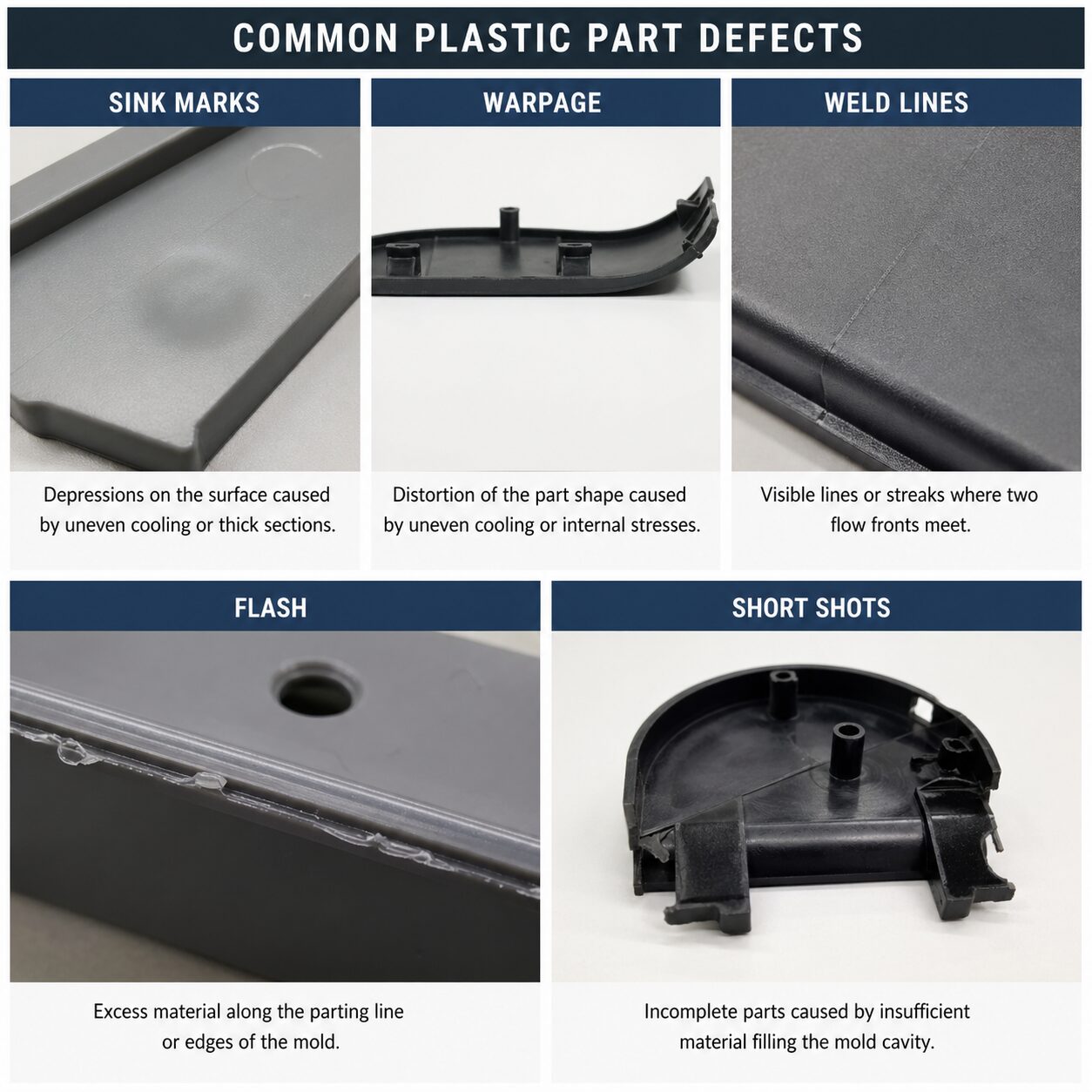
The most expensive design errors are usually predictable. Overly thick walls, poor draft, unnecessary undercuts, weak bosses, unrealistic tolerances, and cosmetic expectations that ignore gate and flow behaviour show up again and again. So does designing around prototype assumptions that do not translate to production steel.
Another common mistake is waiting too long to involve the manufacturer. By the time a team requests mould design, critical part decisions may already be locked. At that point, improvements become compromises instead of straightforward corrections. Glasfil sees the best outcomes when customers bring parts forward while changes are still easy to make.
A good design review should ask practical questions. Where will the part warp first? What surface is truly cosmetic? Can the gate vestige be hidden? Does this undercut add enough value to justify the mechanism? Can the assembly feature survive repeated use? These are not academic questions. They are the difference between a part that merely moulds and a part that performs in production.
The best time to improve a plastic part is before the tool is built. A few careful geometry decisions can remove weeks of delay, reduce mould complexity, and protect part quality long after launch. If your team is developing a new component or refining an existing one, treat design review as a production investment, not a formality.
Contact us today to discuss your project requirements or request a quotation. Let’s build a production process you can depend on.