A housing can look acceptable at the moulding press and still fail where it matters: at the gasket, latch, terminal opening, mounting boss, or mating seam. This electrical enclosure defect-reduction example shows how a production team can move from recurring assembly rejects to controlled, repeatable output by treating the part, mould, material, and inspection process as a single system.
The application is a two-piece injection-moulded electrical enclosure used around a utility control module. The enclosure required a consistent cover fit, secure latch engagement, protection of internal features, and a clean exterior suitable for a customer-facing installation. Initial samples met many individual dimensional checks, yet assembly rejects remained high. That is a common warning sign that the measurement plan is not focused enough on functional relationships.
The Starting Point: Defects at Assembly, Not Just Moulding
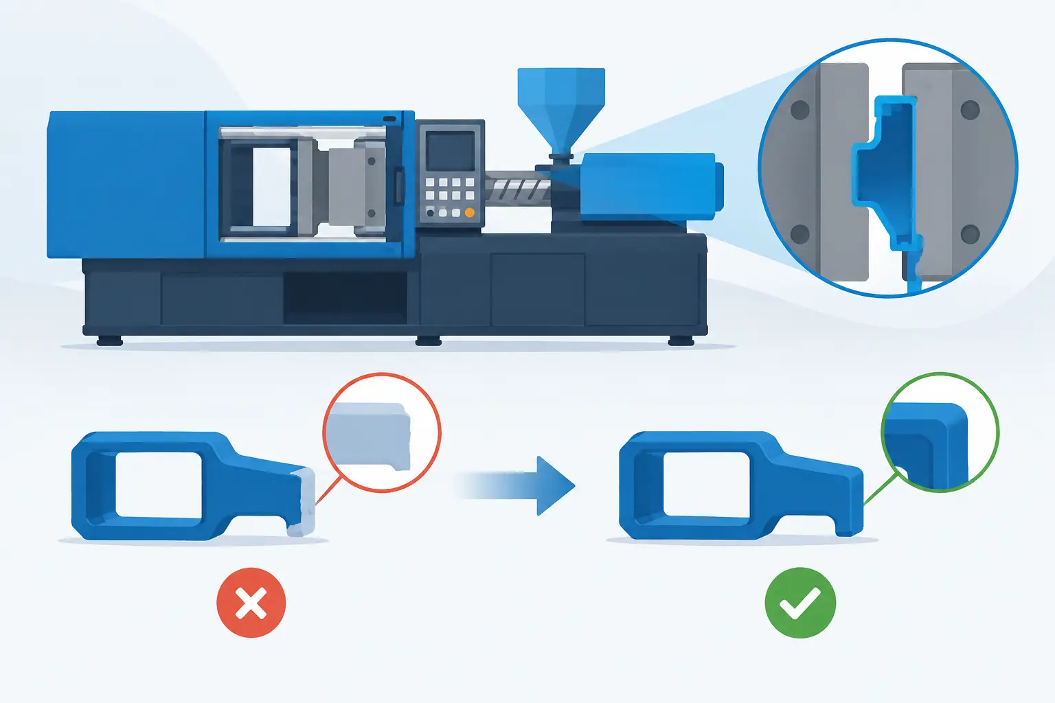
The first production runs showed four connected failure modes: a visible gap along one side of the cover, inconsistent gasket compression, latch tabs that required excessive force to close, and occasional whitening around the latch area after assembly. A cosmetic sink near mounting bosses added another concern.
The moulding team initially adjusted packing pressure and cycle time because the defects appeared to be part-fill and shrinkage issues. That produced limited improvement. Some parts fit better, but process changes that helped one cavity or one feature made another feature worse. The team needed to establish whether the problem came from part design, tooling geometry, material behaviour, or inconsistent moulding conditions.
A useful rule for enclosure programs is simple: do not define a defect only by what is visible. Define it by its functional consequence. A 0.3 mm gap may be acceptable in one area and unacceptable at a sealing interface. A slight warp may be invisible until it prevents a latch from reaching its designed engagement position.
Electrical Enclosure Defect Reduction Example: Root Cause Analysis
The investigation began with a controlled review of rejected and accepted assemblies. Rather than measure every feature again, the team focused on the dimensions that governed the enclosure stack-up: cover flatness, base flatness, latch alignment, perimeter wall position, gasket land height, and boss position relative to the mating edge.
Parts were measured after moulding and again after 24 hours of conditioning. This mattered because the selected polypropylene compound continued to stabilise after ejection. Measurements taken only at the press overstated apparent consistency and missed the movement that affected final assembly.
The findings pointed to a combination of causes. The base section was cooling unevenly because the thick mounting boss region retained heat longer than the perimeter wall. That created a small but repeatable distortion toward the latch side. At the same time, one gate location pushed material flow across a broad cosmetic surface before feeding a critical sealing wall. The resulting orientation and packing pattern increased variation at the gasket land.
The latch whitening was not primarily a material-quality issue. It occurred because the distorted base shifted the latch relationship, forcing operators and automated fixtures to over-flex the cover tab during closure. In other words, the visible stress mark was a downstream symptom of a dimensional and tooling problem.
This distinction prevented an expensive mistake. Changing to a tougher resin might have reduced whitening, but it would not have corrected the sealing gap or excessive closing force. It could also have introduced different shrinkage behaviour, requiring another round of tooling changes.
Changes Made to the Mould and Process
The corrective action combined targeted mould modification with tighter process discipline. The aim was not to chase nominal dimensions on every feature. It was to control the functional geometry that determined enclosure performance.
First, the tooling team revised cooling around the boss and latch-side wall. Additional cooling capacity reduced the temperature difference between the thicker boss section and the surrounding wall during the critical part of the cycle. The mould was also adjusted steel-safe at selected mating features, allowing dimensions to be refined through trial data rather than making an irreversible change too early.
Second, the gate and runner balance were reviewed against the actual fill pattern. A revised gate strategy improved packing at the sealing wall and reduced flow-related variation near the cover interface. Venting was improved at the end-of-fill areas to reduce localised burn marks and unstable surface appearance.
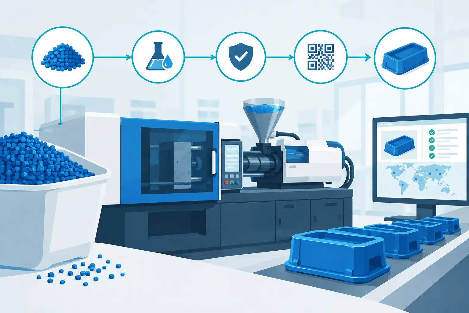
Third, the process window was documented and locked. Barrel temperature, mould temperature, fill speed, pack pressure, pack time, cooling time, and material drying conditions were recorded as controlled production parameters. For hygroscopic materials, moisture control would be especially critical. Even with polypropylene, consistent material handling helps eliminate avoidable variation from lot to lot and shift to shift.
The team also adjusted the assembly fixture. The fixture had been applying closure force at a point that amplified the effect of part variation. Supporting the enclosure closer to the latch and gasket plane gave a more accurate view of true part performance. This is an often-overlooked part of defect reduction: an assembly fixture can create defects, hide defects, or provide useful confirmation that the moulded part is truly functional.
Inspection Shifted From General Dimensions to Functional Risk
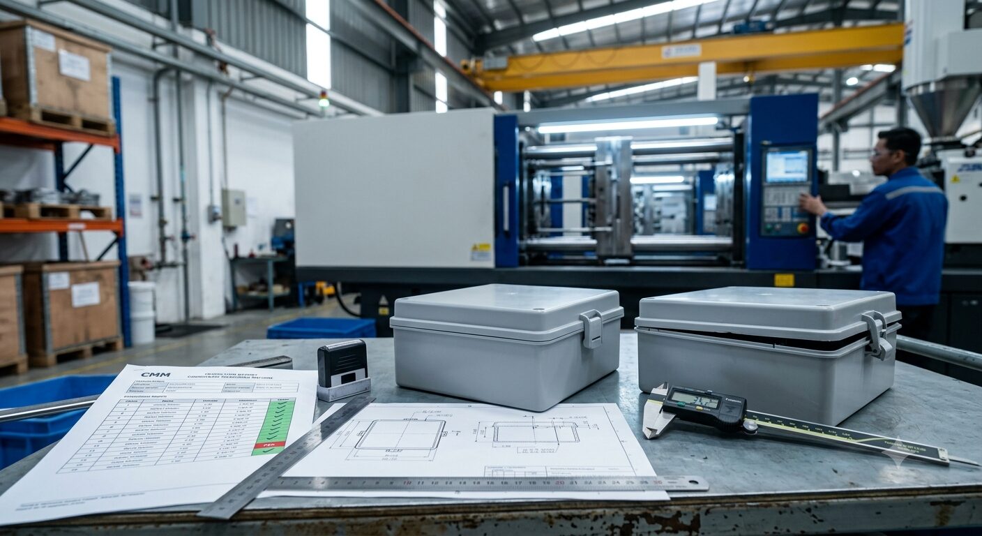
The original inspection plan relied heavily on calliper checks of isolated dimensions. Those checks had value, but they did not predict how the two enclosure halves would behave together. The revised plan added functional inspection at defined intervals.
A go/no-go fixture checked cover closure and latch engagement. A flatness verification method monitored the base sealing plane after conditioning. Gasket land height was measured from a functional datum rather than from a convenient but less relevant external surface. Operators also used approved visual standards for sink, flash, short shots, burn marks, and surface stress.
For a higher-risk electrical application, the plan can go further. Leak testing, ingress protection testing, torque checks at mounting points, and electrical clearance verification may be appropriate depending on the enclosure’s end use. The correct approach depends on the product specification, the required certification path, the operating environment, and the cost of a field failure.
Inspection alone does not improve a weak process. Its role is to verify that the process remains within a proven operating window and to detect drift before defective parts reach assembly or shipment.
Results: Lower Rejects and More Predictable Assembly
After the tooling, process, and fixture changes, assembly rejects in this example fell from approximately 8 per cent to below 1 per cent during the validated production run. Cover-closing force became more consistent, visible latch whitening was largely eliminated, and gasket compression remained within the defined functional range.
The most meaningful result was not simply a lower reject percentage. The production team could explain why the enclosure performed consistently. Cooling balance controlled distortion. Improved filling and packing stabilised the sealing geometry. Functional inspection confirmed the relationship between the two moulded halves before final packing.
That distinction matters when production volumes increase. A part that appears acceptable in a short trial can become costly when minor variation is repeated across thousands of cycles. A documented process window, capable tooling, and inspection tied to actual use conditions make scale-up more predictable.
What This Means for New Enclosure Programs
The fastest way to reduce electrical enclosure defects is to address risk before steel is cut. Product developers should identify the functional datums, gasket interfaces, latch paths, terminal openings, wall-thickness transitions, and cosmetic surfaces during design review. Mould flow analysis and tolerance stack-up analysis are particularly valuable when the enclosure has large flat faces, snap features, tight sealing requirements, or multiple mating components.
Trade-offs still apply. A thicker wall may increase impact resistance but worsen sink and cooling imbalance. A more rigid material may improve enclosure stiffness while making snap features less forgiving. Tighter tolerances can improve fit, but they may add tooling complexity and inspection cost. The right solution depends on the enclosure’s duty cycle, material selection, annual volume, assembly method, and acceptable failure risk.
Glasfil approaches these decisions with in-house design, mould fabrication, modification capability, injection moulding, and quality control under one manufacturing process. That level of control shortens the feedback loop between a defect observed at assembly and the engineering action needed at the mould or press.
The practical lesson is to treat enclosure defects as system failures, not isolated cosmetic events. When tooling design, material behaviour, moulding controls, assembly fixtures, and functional inspection are aligned, the enclosure becomes easier to produce, easier to assemble, and more dependable in the field.
Contact us to discuss your project, request a quotation, or arrange a technical consultation. Our team will help you determine the most cost-effective and reliable way to manufacture your part.