A production-ready plastic part begins long before the first machine cycle. Understanding how injection molding works helps product teams make better decisions about geometry, material, tooling investment, lead time, and the cost of every unit produced. For OEMs and industrial buyers, the process is not simply melting plastic and filling a mold. It is a controlled manufacturing system where part design, tooling accuracy, processing parameters, and inspection must work together.
How Injection Molding Works, Step by Step
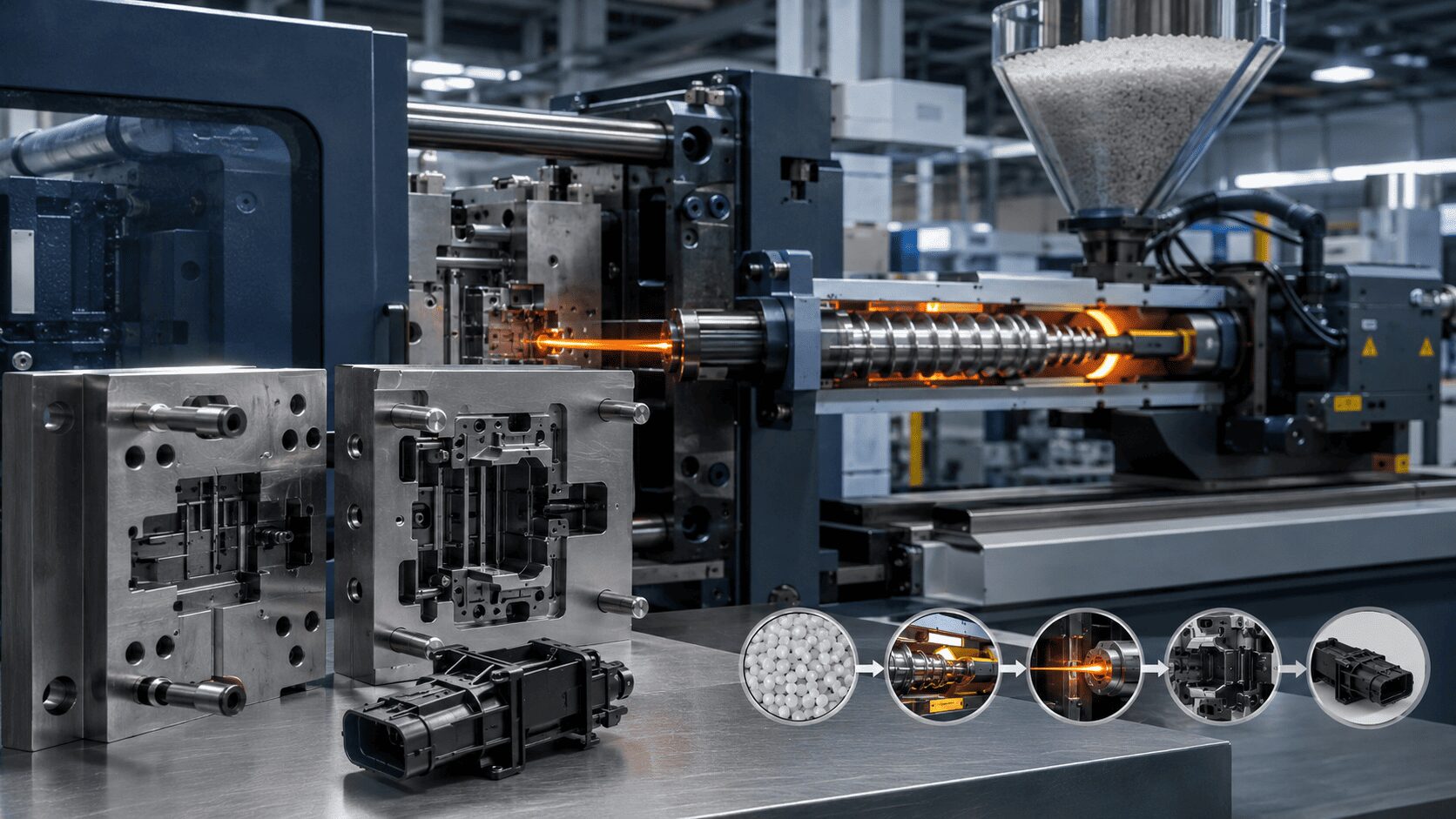
Injection molding forms plastic components by melting polymer resin, injecting it into a closed steel or aluminum mold under pressure, cooling it until it becomes stable, and ejecting the finished part. The cycle repeats automatically, often producing thousands or millions of consistent components from the same tool.
The basic sequence is straightforward. Plastic pellets enter a hopper and move into a heated barrel. A rotating screw conveys, melts, and meters the material in front of the screw tip. Once the correct shot size is prepared, the screw moves forward like a plunger and pushes molten plastic through the mold’s runner system and gates into the part cavity.
The mold remains clamped shut while the plastic fills every intended area. Pressure is then maintained briefly to compensate for shrinkage as the material cools. After sufficient cooling, the mold opens, ejector pins release the part, and the mold closes again for the next cycle.
That description is simple by design. In production, every stage affects the next. A small change in melt temperature, gate location, cooling time, or clamp force can alter appearance, dimensions, strength, cycle time, and cost.
The Mold Is the Production System
The injection mold determines much more than the shape of a plastic part. It controls how material enters the cavity, where air escapes, how the component cools, how it is released, and how consistently it can be produced over time.
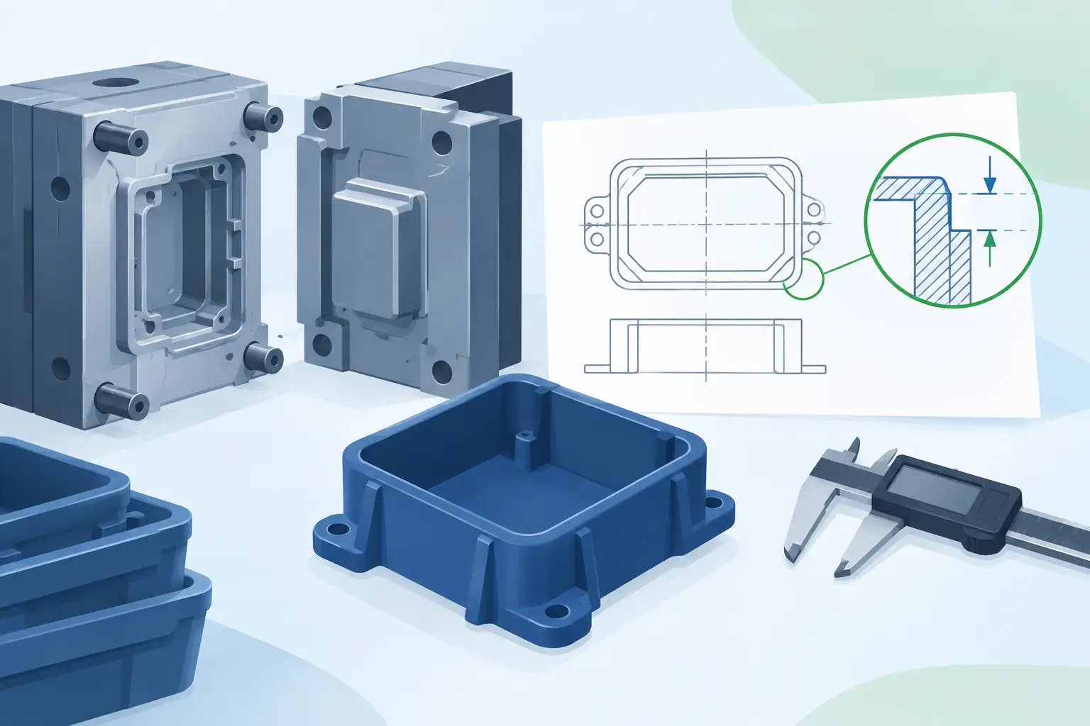
A typical mold includes a cavity side and a core side. When they close, the space between them creates the final part geometry. Cooling channels circulate temperature-controlled water or oil through the tool. Ejector pins, sleeves, or plates push the cooled part out after the mold opens.
The runner system carries molten material from the injection machine nozzle to the cavity. In a cold-runner mold, the runner solidifies with each shot and is separated or reground when appropriate. A hot-runner system keeps material molten up to the gate, reducing runner waste and often improving automation. The best choice depends on resin, production volume, part requirements, color-change frequency, and tooling budget.
Tooling decisions should be made around the expected production program. A prototype or low-volume part may justify a simpler tool and a shorter development path. A high-volume automotive, electrical, or utility component may require hardened steel, engineered cooling, multiple cavities, automated part handling, and planned maintenance access. Buying a tool without considering its operating life is a common source of avoidable cost.
Why Part Design Matters Before Tooling Starts
Injection molding can produce complex geometry efficiently, but it does not remove the need for disciplined design. Uniform wall thickness is usually the starting point because thick sections cool more slowly and can create sink marks, internal voids, or distortion. When added strength is needed, ribs and gussets are often more effective than simply increasing wall thickness.
Draft angle is equally important. Even a highly polished mold cannot reliably release a part with vertical walls and no draft. The required draft depends on material, texture, part depth, and surface finish, but the principle remains the same: parts must release cleanly without scuffing or excessive ejection force.
Designers must also account for material shrinkage. Plastic contracts as it cools, and each resin behaves differently. Toolmakers calculate shrinkage allowances so the cooled part reaches the required dimensions. Tight tolerances are possible, but they should be applied where function truly requires them. Over-specifying tolerances raises tooling complexity, inspection effort, and rejection risk.
Material Selection Drives Performance
The resin is not a cosmetic choice. It establishes the part’s mechanical behavior, chemical resistance, heat performance, electrical properties, surface quality, and long-term durability.
Commodity materials such as polypropylene, polyethylene, and polystyrene can be cost-effective for many consumer and industrial applications. Engineering resins such as ABS, polycarbonate, nylon, POM, and reinforced compounds serve more demanding requirements. Glass-filled grades can increase stiffness and strength, but they may require more wear-resistant tooling and can affect surface finish or warpage.
Material selection should reflect the actual operating environment. A bathroom accessory may need moisture and chemical resistance. An electrical enclosure may require flame performance, insulation properties, and dimensional stability. An automotive under-hood component faces heat, vibration, fluids, and long service life. The right resin is the one that meets the functional requirement at an acceptable total production cost, not necessarily the most expensive grade.
Colorants, UV stabilizers, impact modifiers, flame retardants, and recycled content can also change processing behavior. These additions should be reviewed during development rather than treated as late-stage purchasing details.
Filling, Packing, Cooling, and Ejection
Once the mold and material are ready, process control becomes the central discipline. The machine must apply the right temperature, injection speed, pressure, and timing for the specific part and resin.
During filling, the objective is to deliver molten plastic into the cavity quickly enough to avoid premature freezing, but not so aggressively that it causes burn marks, jetting, flash, or excessive internal stress. Mold vents allow displaced air to escape. Poor venting can leave burns, incomplete fill, or inconsistent surfaces even when the machine settings appear correct.
After the cavity fills, packing pressure adds material while the gate remains molten. This stage helps reduce shrinkage-related defects and stabilizes critical dimensions. Too little packing can lead to sinks and short parts. Too much can create stress, flash, or difficult ejection.
Cooling often consumes the largest portion of the overall cycle. The part must become rigid enough to be ejected without deformation, but unnecessary cooling time reduces output and raises unit cost. Efficient cooling-channel design is therefore one of the highest-value elements of mold engineering.
Ejection is the final mechanical step. The part must leave the mold without scratches, distortion, stress whitening, or damage to fine features. Complex components may use slides, lifters, unscrewing mechanisms, or specialized ejection systems to create undercuts and functional details that a simple two-plate mold cannot produce.
What Causes Defects in Injection-Molded Parts?
Most molding defects are symptoms, not isolated events. A short shot may result from insufficient material, a cold flow path, inadequate venting, or a gate that freezes too early. Warpage can come from uneven wall thickness, unbalanced cooling, fiber orientation, inconsistent packing, or an unsuitable material choice.
Flash occurs when molten plastic escapes at the mold parting line or around inserts. It may indicate excessive pressure, insufficient clamp force, worn tooling, or damage at the sealing surfaces. Sink marks often point to thick sections, poor packing, or gates that are too small or too far from the affected area.
The right response is not to keep adjusting machine settings until the defect appears less visible. Effective troubleshooting starts with the part, tool, material, and process as one system. That is why in-house mold modification capability is valuable when a production issue requires a tooling correction rather than another processing adjustment.
Quality Is Built Into the Cycle
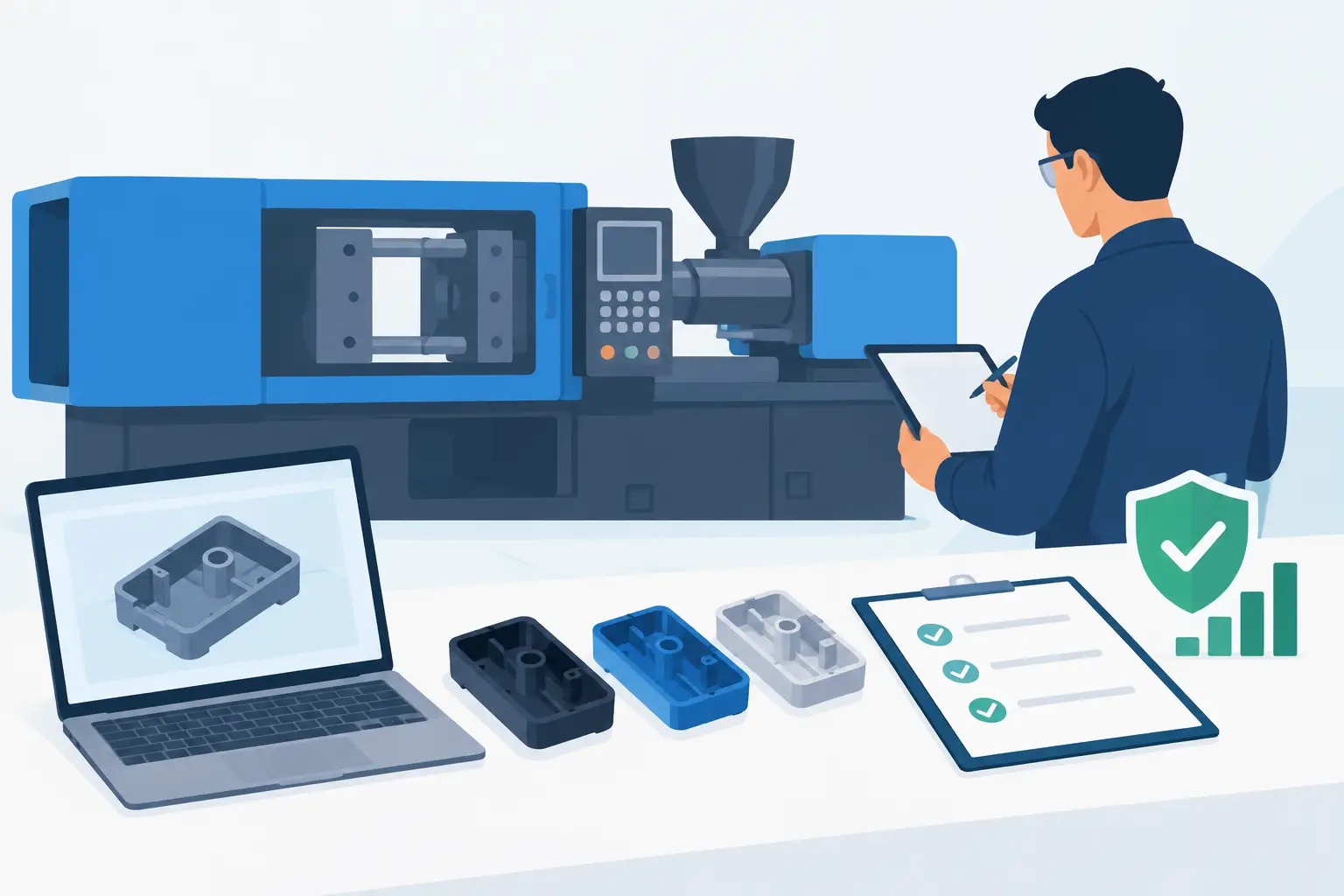
Consistent injection molding relies on repeatable conditions. Resin should be handled and dried according to supplier requirements. Machine settings must be documented and controlled. Tool temperatures, cycle times, cavity pressure where applicable, and finished-part dimensions should be monitored against established standards.
Quality checks may include visual inspection, dimensional measurement, weight verification, assembly tests, color evaluation, and functional testing. The inspection plan should focus on features that affect fit, safety, sealing, electrical performance, or customer-facing appearance. A part can look acceptable and still fail in assembly if its critical dimensions are not controlled.
For repeat orders, mold maintenance is part of quality assurance. Gates, vents, ejectors, cooling circuits, and sliding components wear over time. Preventive maintenance protects cycle stability and helps avoid unplanned stoppages that can disrupt a supply chain.
From Concept to Repeat Production
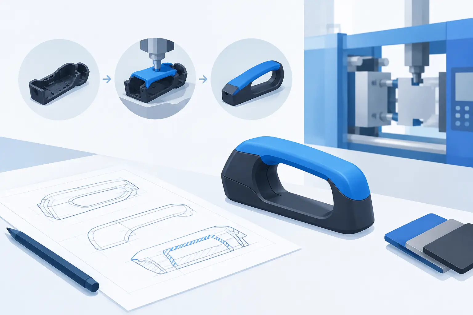
The strongest injection molding programs begin with an early manufacturability review. Before steel is cut, the manufacturer should assess wall thickness, draft, gate location, parting-line placement, tolerances, cosmetic surfaces, resin behavior, expected volume, and secondary operations. This prevents expensive changes after the tool is built.
For a buyer, the practical question is not only whether a supplier can mold a sample. It is whether that supplier can engineer the tool, validate the process, control changes, maintain the mold, complete finishing operations, and deliver repeatable parts on schedule. Glasfil supports this integrated path with in-house mold design, fabrication, modification, molding, quality control, and secondary processing.
Injection molding rewards preparation. When the part is designed for the process, the tool is built for the production demand, and the process is validated with measurable controls, it becomes one of the most efficient methods for manufacturing custom plastic components at scale. The best next step is to review the part requirements before tooling begins, while changes are still fast, practical, and cost-effective.
Contact us to discuss your project, request a quotation, or arrange a technical consultation. Our team will help you determine the most cost-effective and reliable way to manufacture your part.