A grip that separates from its housing, a seal that leaks after thermal cycling, or an insert that shifts by a fraction of a millimeter can turn a promising part into a costly production problem. This overmolding design guide focuses on the decisions that determine whether a two-material component performs consistently at production scale: material compatibility, interface geometry, tooling control, and process validation.
Overmolding joins a first-shot substrate or insert with a second material, commonly a softer thermoplastic elastomer (TPE) or thermoplastic polyurethane (TPU). The result can combine structure, grip, sealing, insulation, appearance, or vibration control in one component. The process is widely used for tool handles, electrical enclosures, automotive controls, bathroom products, medical-adjacent devices, and consumer hardware. It is also less forgiving than a standard single-material molded part.
Start With the Function of Each Material
A successful overmolded part begins with a clear division of labor. The substrate normally provides stiffness, dimensional stability, mounting features, and load-bearing strength. The overmold material contributes grip, cushioning, sealing, impact protection, or a visual distinction.
Do not select the soft material based on Shore hardness alone. A 60 Shore A TPE may feel right in a prototype but fail the actual application if it has poor chemical resistance, insufficient tear strength, inadequate UV stability, or weak adhesion to the substrate. Define the operating environment before selecting a resin: temperature range, contact with oils or cleaners, outdoor exposure, repeated flexing, electrical requirements, and expected service life all matter.
The substrate is equally important. Polypropylene often pairs well with certain TPE grades because the materials can form a chemical bond under the right molding conditions. ABS, polycarbonate, nylon, and acetal each require more specific material choices. Some combinations rely mainly on mechanical interlock rather than molecular adhesion. That can be appropriate, but it must be designed deliberately.
Ask the resin supplier and molder to confirm compatibility for the exact grades under consideration. Broad material-family charts are useful for early screening, not final engineering approval. Fillers, colorants, flame-retardant packages, recycled content, and moisture levels can all affect bonding behavior.
Overmolding Design Guide: Build a Reliable Interface
The interface between the first and second shots is the critical design zone. It needs enough contact area to resist peeling and shear, but it also needs geometry that can be molded, vented, cooled, and released from the tool consistently.
Where chemical adhesion is strong, a broad, clean interface may be sufficient. Where the bond is limited or the part sees pulling forces, use mechanical retention features. Through-holes, undercuts, windows, ribs, grooves, and wraparound sections allow the overmold material to lock around the substrate. A soft grip covering the sides of a rigid handle, for example, is more secure when the material wraps around edges or passes through designed openings rather than ending at a straight boundary line.
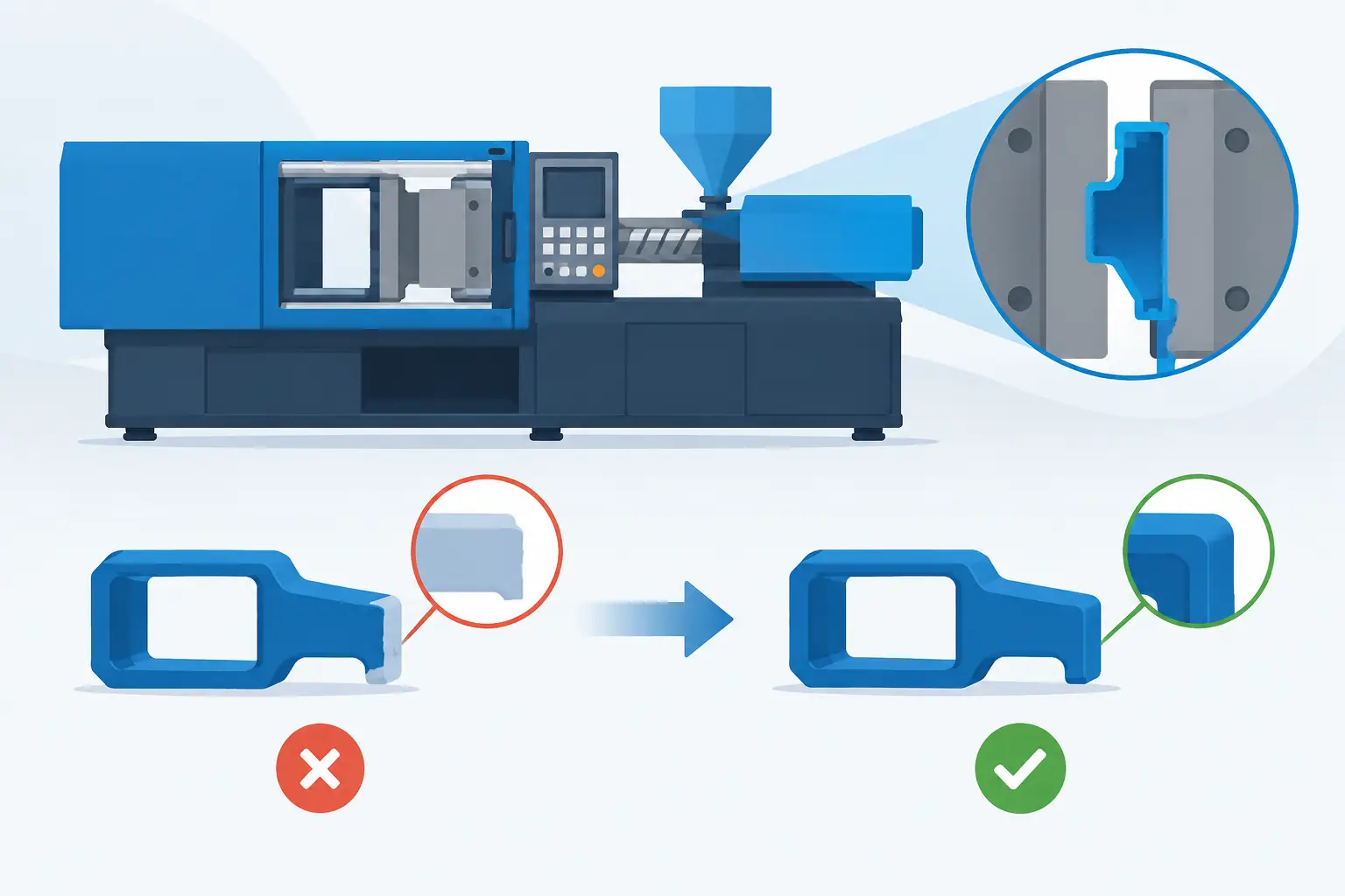
Avoid sharp internal corners at the interface. They concentrate stress and can cause the soft material to tear during use. Use radii where practical, especially in high-flex or high-load locations. Also avoid thin, unsupported lips of soft material. They may look acceptable when newly molded but can deform, peel, or become difficult to control during production.
Wall thickness deserves the same attention as interface shape. Large thickness changes in the overmold can lead to sink, uneven cooling, surface defects, and variable shrinkage. Maintain a reasonably uniform section whenever possible. If a thick soft-touch area is required, support it with substrate geometry rather than simply adding more elastomer.
Control Tolerances Before Tooling Begins
Overmolding is a process of locating one component precisely inside a second molding operation. That makes substrate tolerances, fixture references, and part handling central to success.
The first-shot part must locate in the second-shot tool using features designed for repeatable positioning. Cosmetic surfaces and flexible edges are poor choices for these references. Use stable datums, holes, pads, or rigid geometric features that the tool can hold without distortion. The locating strategy should prevent translation and rotation while allowing predictable part ejection.
Specify critical dimensions based on function, not habit. If an overmold creates a seal, inspect the compressed sealing geometry. Assuming that it covers an electrical connection, inspect material coverage and positional clearance. If it creates a hand grip, focus on coverage boundaries, adhesion, and feel rather than applying unnecessarily tight tolerances to nonfunctional surfaces.
Shrinkage must be calculated for both materials. The first shot has already shrunk before the second shot is applied, while the overmold material will shrink after molding. Differential shrinkage can cause curl, stress, gaps, or visible witness lines. This is one reason design, tooling, and molding teams should review the part together before steel is cut.
Design for the Molding Process, Not Just the CAD Model
A CAD model does not show how resin will fill a cavity, where air will be trapped, or how a part will be transferred between shots. Tooling decisions shape the final result.
Gate placement should drive material into the overmold area in a way that limits weld lines in high-stress or cosmetic locations. The flow path must fill thin sections without freezing off and without applying excessive pressure to the substrate. For a soft overmold, a poorly placed gate can create visible flow marks or push the insert out of position.
Venting is equally significant. Air trapped at the end of fill can cause burn marks, incomplete filling, and weak bonding. Thin grip ribs, enclosed mechanical locks, and deep texture details need a realistic venting plan. Cooling should be considered at the same stage. Uneven cooling increases cycle time and can create dimensional variation, particularly when a large soft overmold sits on one side of a rigid substrate.
The appropriate process depends on volume, geometry, and quality requirements. Insert overmolding places a separate component, such as a metal pin, cable, or molded substrate, into the mold before injection. Two-shot molding uses a dedicated tool and machine sequence to mold both materials in a controlled cycle. Two-shot tooling can reduce handling and improve repeatability at higher volumes, while insert overmolding may be better suited to lower volumes, complex inserts, or staged assembly requirements.
Plan for Appearance and Long-Term Use
A visible boundary between materials is a design feature, not an afterthought. Decide whether the transition should be crisp, recessed, wrapped around an edge, or hidden beneath a functional detail. A boundary placed on a high-contact edge is more likely to show wear and may be more vulnerable to peeling.
Texture can improve grip and mask minor flow variation, but aggressive texture has limits. Deep texture can complicate filling, release, cleaning, and cosmetic consistency. Consider how the selected texture will behave after repeated contact with oils, water, dust, or cleaning agents.
Color matching requires production-level testing. Soft materials can appear different than rigid substrates even when they use the same nominal color. Surface texture, gloss, wall thickness, and resin transparency alter the perceived result. If color is brand-critical, approve molded plaques or production-intent samples rather than relying only on digital renderings or pellet samples.
Long-term validation should match the actual product risk. Typical checks include peel or pull testing, thermal cycling, humidity exposure, chemical exposure, abrasion, drop testing, and repeated flexing. Electrical and automotive applications may require additional performance testing. The goal is not to run every possible test. It is to test the failure modes that would matter to the customer, installer, operator, or end user.
Use Prototyping to Resolve Production Questions
Prototype parts are valuable when they answer specific manufacturing questions. A visual prototype can confirm size and ergonomics, but it cannot prove adhesion, cycle stability, or production tolerances. For overmolding, the most useful prototypes use intended or closely representative materials and realistic interface geometry.
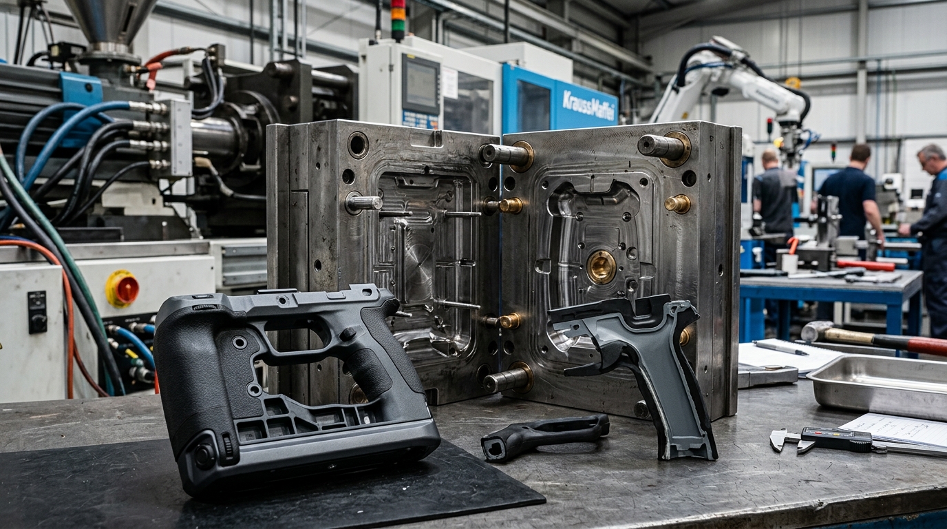
Early samples should be reviewed for bond strength, flash at the material boundary, insert movement, coverage consistency, surface quality, and warpage. Tool adjustments are normal, particularly around gates, vents, shutoffs, and locating features. The advantage of working with an integrated manufacturer is direct control of those iterations. Glasfil maintains in-house mold design, fabrication, modification, molding, and quality processes so findings from sampling can be translated into corrective tooling action without unnecessary handoffs.
Make the Part Easy to Inspect and Scale
A production-ready design includes a practical inspection strategy. Define acceptance criteria for the bond line, overmold coverage, flash, color, critical dimensions, and functional retention features. Where possible, use objective gauges or fixtures rather than visual judgment alone.
Also consider packaging and assembly. Soft surfaces can pick up marks, deform under stacking loads, or adhere to protective films. A part that molds well but arrives damaged is not a successful production outcome. Packaging trials should be part of the launch plan for cosmetic or soft-touch components.
The best time to solve an overmolding risk is before the first tool trial, when a revised radius, retention window, or locating pad costs little to change. Treat the material interface as a functional engineering feature, give the toolmaker clear production requirements, and validate the part against its real operating conditions. That approach produces components that look intentional on day one and continue performing after thousands of cycles.
Contact us to discuss your project, request a quotation, or arrange a technical consultation. Our team will help you determine the most cost-effective and reliable way to manufacture your part.