A part can come out dimensionally acceptable, pass a quick visual check, and still create problems the moment it reaches assembly or the customer. Sink marks are one of those defects. If you are asking what causes sink marks, the short answer is uneven material shrinkage during cooling. The useful answer is more specific: sink marks usually appear where part geometry, resin behaviour, mould design, and processing conditions allow the plastic core to keep shrinking after the outer surface has already solidified.
That is why sink marks are rarely a one-variable issue. They are usually the visible result of several decisions made upstream – wall thickness, rib design, gate location, pack pressure, hold time, cooling layout, and even resin selection. In production, the most effective fix comes from identifying which of those variables is controlling the defect on that specific part.
What causes sink marks during moulding?
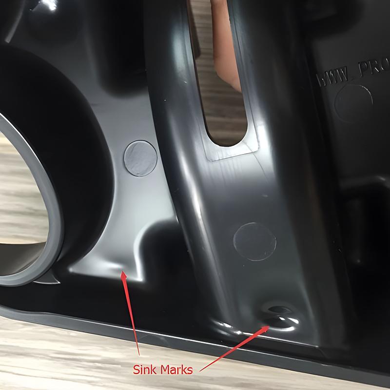
Sink marks are shallow depressions on the surface of an injection-moulded part. They often show up above ribs, bosses, thick sections, or transitions where material mass is concentrated. The plastic on the outside of the part cools first, forming a skin. The material inside stays hotter for longer. As that hotter core cools, it contracts. If there is not enough additional material packed into the cavity to compensate for that shrinkage, the surface pulls inward and leaves a visible sink.
This is why sink marks are so common in otherwise well-designed programs. A feature may be structurally necessary, such as a screw boss or reinforcement rib, but it also creates a thicker local section. That added mass changes cooling behaviour and increases the risk of differential shrinkage.
The defect is cosmetic in many cases, but not always. A visible sink can signal internal stress, inadequate packing, or poor density distribution in the part. On cosmetic housings, consumer-facing surfaces, and precision assemblies, that can quickly become a reject issue rather than a minor appearance concern.
The main reasons sink marks happen
Thick wall sections and mass concentration
Part geometry is usually the first place to look. Thick sections cool more slowly than thin sections, and abrupt wall changes make the difference even worse. A nominal wall may run well across most of the part, but a heavy boss base or thick rib intersection can create a hot spot. The outside freezes, the interior continues to shrink, and the surface caves slightly.
This is why wall consistency matters so much in injection moulding. Uniform walls allow the part to cool at a more even rate. Once geometry becomes uneven, process settings can help, but they may not fully overcome the design itself.
Poor rib and boss design
Ribs and bosses are essential functional features, but they are also common sink generators. If a rib is too thick relative to the nominal wall, or a boss base is oversized, it creates extra material volume directly beneath the visible surface. That hidden mass is enough to produce a sink even when the outside of the part looks simple.
In many programs, the issue is not the presence of ribs or bosses. It is the ratio. A well-proportioned rib can add stiffness without creating cosmetic damage. An overbuilt one often creates a predictable quality problem.
Inadequate packing pressure or hold time
After the cavity fills, the machine must continue packing material into the part while the gate remains open. This compensates for volumetric shrinkage as the plastic cools. If packing pressure is too low or hold time is too short, the cavity does not receive enough additional material. The part may look full when it leaves the fill phase, but the internal material loss during cooling shows up later as a sink.
This is one of the most common processing causes. It is also one of the first areas a moulder should test, because the correction can be straightforward if the gate is sized correctly and the part is still packable.
Gate size and gate location
Even with sufficient machine pressure, the gate has to support packing effectively. If the gate is too small, it freezes too early. Once that happens, no more material can enter the cavity to offset shrinkage in thicker areas. The result is often a sink near the last areas to densify or in regions far from the gate.
Gate location matters just as much. If material has to travel too far before reaching a heavy section, pressure loss may limit how well that area packs out. A different gate position, a larger gate, or a revised runner strategy can dramatically change sink performance.
Insufficient cooling or poor mould temperature control
Sink marks are strongly tied to thermal behaviour. If cooling is uneven, or if a local area of the tool retains too much heat, the part may shrink inconsistently from one section to another. Thick features already have a cooling disadvantage. Inadequate water line placement or poor thermal balance compounds it.
Lowering mould temperature is not always the right answer by itself. In some cases, it improves skin formation but increases internal stress or hurts surface quality elsewhere. The real objective is controlled, consistent heat removal across the cavity.
Material behaviour and shrink rate
Different resins shrink differently. Semi-crystalline materials generally have higher shrinkage than amorphous materials, which can make sink sensitivity more pronounced. Filled materials may reduce shrinkage in some situations, but they can also introduce flow limitations or surface issues depending on the application.
Material choice should match both function and manufacturability. A resin that performs well mechanically may require tighter control of wall thickness, packing, and cooling. That is not a reason to avoid it, but it is a reason to engineer the part and process around it from the start.
What causes sink marks most often in real production?
In production environments, sink marks usually come from a combination of part design and process limits rather than a single machine setting. A heavy feature may be technically moldable, but only if the gate stays open long enough to pack it. The gate may be adequate, but the cooling layout may leave a hot zone. Or the tool may be capable, but cycle time pressure pushes the process toward early ejection and inconsistent results.
That is where many teams lose time. They chase the symptom at the press when the root cause was designed into the part, or they redesign the part when the issue could have been corrected through tooling or process development. The right path depends on where the biggest constraint sits.
How to reduce or prevent sink marks
The strongest prevention method is still part design. Keep wall thickness as uniform as possible. Core out heavy sections. Size ribs and bosses correctly relative to the nominal wall. Avoid sudden transitions in thickness when a gradual change can achieve the same function. These decisions reduce defect risk before the mould is ever cut.
Once tooling is in play, gate strategy becomes critical. The part must be able to pack dense material into the sections that stay hot the longest. That may require moving the gate closer to a heavy feature, increasing gate size, or adjusting runner balance. Mould cooling should also be reviewed early, especially in cosmetic or tight-tolerance parts.
At the press, pack pressure, hold time, melt temperature, mould temperature, and cooling time all need to be developed together. Raising pack pressure can help, but only to the point where the gate remains open and the tool supports the pressure safely. Extending hold time can reduce sinks, but if the gate has already frozen, extra time adds cycle cost without improving the part.
Material selection also deserves attention. If two resins meet performance requirements, the one with more stable shrink behaviour may offer a better overall production window. That trade-off matters when appearance and repeatability carry the same weight as mechanical properties.
Why sink marks should be addressed early
Sink marks are rarely just a surface flaw. They affect perceived quality, and they often signal a deeper issue in how the part is being filled, packed, and cooled. In sectors like automotive, electrical housings, bathroom accessories, and utility components, issues can turn into rework, scrap, line disruption, or customer complaints.
For OEMs and product teams, the higher cost is usually time. If a sink problem appears after tooling is built, the fix may involve process trials, mould modification, or design revision. All of that is manageable, but it is far faster when the moulder has in-house control over tooling, processing, and quality review. That integrated approach is exactly where a full-service injection moulding partner like Glasfil can reduce delays and keep a project moving.
The practical question is not only what causes sink marks. It is during the product realisation cycle that they are being identified. The earlier they are engineered out, the less they cost.
If a moulded part shows even minor surface depression above a rib, boss, or thick wall, treat it as useful feedback. The part is telling you where heat, pressure, and geometry are no longer in balance – and that is the moment to fix the process before the defect becomes standard output.
Contact us today to request a quote or schedule a discussion with our technical team.