A drawing can specify a tight dimension, but your mold, resin, machine, and measurement method must all repeatedly hold it. That reality drives true tolerance improvement in injection molding. A part that measures correctly in a first sample but drifts across cavities, shifts after conditioning, or changes between production runs is not under control.
For OEMs and product teams, tolerance improvement starts long before the first production cycle. It requires a practical review of part geometry, material behavior, tooling strategy, process windows, and inspection criteria. Tight tolerances are achievable, but they require trade-offs in mold cost, cycle time, material selection, and validation effort.
Start With a Tolerance That Fits the Part’s Function
Not every dimension deserves identical control. Focus your engineering effort on features that locate a part, support a seal, engage mating components, carry loads, or define visual appearance. A non-functional wall or open profile rarely requires the tight tolerance of a bearing seat, snap feature, thread, or connector interface.
Over-tolerancing quickly inflates costs. It demands higher-precision machining, complex mold construction, longer sampling, tighter monitoring, and frequent inspection. It also triggers false rejections for variations that do not affect part performance.
Identify critical-to-function features first and establish realistic limits for non-critical geometry. This strategy gives your tooling and molding teams clear priorities: protect vital dimensions while running an efficient production process.
Consider the geometry, not only the nominal size
Long, thin walls, unsupported tabs, deep ribs, large flat surfaces, and asymmetric features are more likely to move as the part cools. A nominal dimension may be easy to hold near the gate and more difficult to control at the far end of the flow path. Similarly, internal features can shrink differently from external features because of cooling and packing conditions.
Tolerance analysis should account for where the feature sits in the mold, how it fills, and whether it is affected by localized shrinkage or post-mold warpage. A practical moldability review often identifies issues that a drawing alone cannot reveal.
Improve Molded Part Tolerances Through Material Control
Every resin has a shrinkage range, and that range is influenced by grade, filler content, moisture, melt temperature, mold temperature, packing pressure, and part geometry. Switching from one grade to another, even within the same polymer family, can change the final dimensions enough to affect a critical fit.
Filled materials generally offer better dimensional stability than unfilled grades. Glass-filled nylon, for example, may reduce overall shrinkage, but it can also introduce directional behavior. The material may shrink differently in the flow direction than across it. That can make a long rectangular part harder to control if gate location and fiber orientation are not considered.
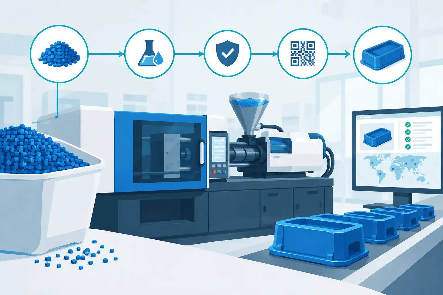
Moisture-sensitive materials need disciplined drying. Nylon, PET, PC, and other hygroscopic resins can produce dimensional variation, surface defects, and reduced mechanical performance when processed with excessive moisture. Resin storage, dryer performance, drying temperature, and drying time should be treated as controlled production inputs, not background housekeeping tasks.
Colorant and regrind policies also matter. If a tight-tolerance part uses recycled material, the allowable percentage and handling method should be established during validation. Changes in material history can affect flow, shrinkage, and consistency.
Build Dimensional Control Into the Mold
A mold cannot correct every design issue, but high-quality tool design provides the foundation for repeatable dimensions. Cavity and core steel selection, machining accuracy, shutoff design, venting, cooling layout, ejection, and gate placement all affect the part’s final condition.
Cooling deserves particular attention. Uneven mold temperature creates uneven shrinkage, which leads to warpage and dimensional drift. Large parts, parts with thick-to-thin transitions, and components with broad flat surfaces benefit from cooling circuits designed around the actual thermal load rather than simple channel placement.
Gate location controls how the cavity fills and packs. It affects weld line location, pressure transfer, fiber orientation, shrinkage direction, and the ability to pack out distant features. Moving a gate can improve one critical dimension while creating a new risk elsewhere, so this decision should be based on part function and flow analysis where appropriate.
For demanding applications, mold inserts can be designed for controlled adjustment. This gives the tooling team a practical route to correct steel after trial measurements without compromising the rest of the cavity. It is far more effective than trying to force a poorly sized tool into specification through machine settings alone.
Use cavity-specific thinking
Multi-cavity molds bring productivity, but each cavity must be evaluated independently during qualification. A part may meet specification when samples are mixed together while one cavity consistently runs near a limit. Over time, that variation can become a quality issue.
Cavity pressure balance, runner design, cooling performance, and individual steel condition all contribute to cavity-to-cavity variation. Marking parts by cavity during sampling and inspection makes it possible to identify the source of a dimensional problem early.
Establish a Stable Molding Process Before Chasing Numbers
A tight dimension should be held by a stable process, not by constant operator adjustment. Once a mold is running, the process team should establish defined operating ranges for melt temperature, mold temperature, fill speed, transfer position, packing pressure, holding time, cooling time, and cycle time.
The key is understanding which variables drive each critical feature. A dimension that is sensitive to packing may move when hydraulic pressure changes. A flatness issue may be more sensitive to cooling balance or ejection timing. A hole diameter may be affected by core temperature, material lot variation, or post-mold conditioning.
Short-shot studies, pressure studies, and controlled process trials help separate cause from coincidence. Instead of changing several settings at once, vary one defined parameter within a planned range and measure the result. This produces usable process knowledge and helps establish a reliable operating window.
Cycle time should not be reduced blindly. Removing cooling time may increase output in the short term, but a part that is ejected too hot can distort in the fixture, on the conveyor, or in the shipping container. The correct cycle is the shortest one that consistently produces a stable, conforming part.
Measure Parts the Same Way They Will Be Accepted
Measurement variation is often mistaken for molding variation. If different operators use different fixturing, caliper pressure, measurement locations, or conditioning times, the inspection data will not show the true condition of the process.
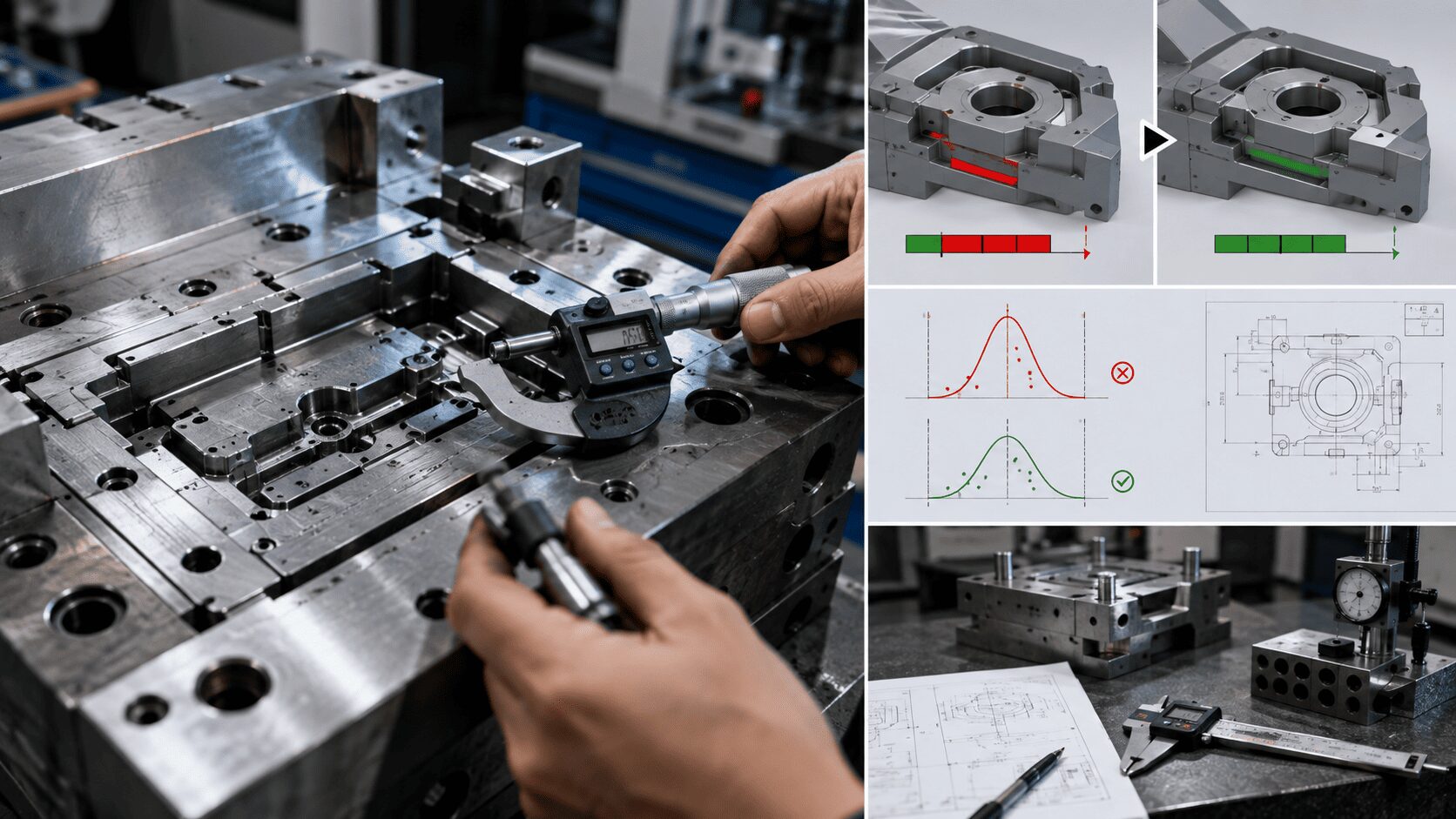
Critical dimensions need a clear inspection method. That may include a dedicated checking fixture, go/no-go gauge, coordinate measuring machine program, optical system, or functional assembly gauge. The right choice depends on the feature, tolerance band, production volume, and risk of an incorrect result.
Part conditioning must also be defined. Some materials continue to change after molding as they cool, absorb moisture, or release internal stress. A nylon component measured immediately after molding may not match the same component measured after 24 hours in a controlled environment. If the customer accepts the part after conditioning, validation should use that same condition.
For production programs, statistical process control can show whether a dimension is centered and capable before parts exceed limits. Capability data is most useful when it is tied to a stable tool, defined material, approved measurement method, and locked process settings.
Plan for Tool Wear and Production Change
A mold that holds tolerance at launch will not stay there automatically. Gates wear, shutoffs degrade, ejector pins can loosen, cooling passages can scale, and moving components require maintenance. Preventive maintenance protects dimensional control as much as it protects uptime.
Tooling records should track adjustments, repairs, cavity-specific observations, and recurring dimensional trends. When a feature starts moving toward a specification limit, early intervention is usually simpler than sorting production or making an urgent correction after a customer rejection.
Changes also need control. A new resin lot, alternate supplier, color change, machine transfer, mold repair, or packaging revision can affect the final part. Not every change requires a full requalification, but critical dimensions should be verified whenever a variable with known influence has changed.
Work With a Manufacturer That Controls the Full Chain
Molds that hold tolerance at launch do not stay that way automatically. Gates wear, shutoffs degrade, ejector pins loosen, cooling lines scale up, and moving slides require routine care. Preventive maintenance protects dimensional precision as much as it guards uptime.
Track tooling adjustments, repairs, cavity-specific observations, and recurring dimensional trends in your maintenance logs. Intervening when a feature drifts toward a tolerance limit is simple; sorting scrap after customer rejection is not.
Reverify critical dimensions whenever key variables change:
-
New resin lots or alternate material suppliers
-
Colorant ratio adjustments
-
Machine transfers or major press maintenance
-
Tool repairs and cavity modifications
-
Packaging or storage revisions
The fastest path to tight tolerances eliminates handoffs between design, tooling, production, and quality teams. Separate vendors often debate assumptions when dimensions shift. Integrated teams trace variation directly from CAD models to mold steel, press parameters, and inspection gauges.
At Glasfil, we manage mold design, tool fabrication, modifications, injection molding, secondary processing, and quality control within a single facility. This unified control accelerates tool adjustments, refines process windows, and guarantees part consistency across production runs.
Contact us to discuss your project, request a quotation, or arrange a technical consultation. Our team will help you determine the most cost-effective and reliable way to manufacture your part.