A part can pass inspection at the start of a shift and begin showing sinks, flash, or short shots a few hours later. For an OEM, that is not simply a molding issue. It can delay assembly, increase sorting labor, put delivery dates at risk, and turn a predictable production run into a costly containment exercise. This plastic defect reduction example shows how a manufacturer can move from repeated defects to controlled, repeatable output by addressing the whole production system.
The Plastic Defect Reduction Example: Sink Marks on a Housing
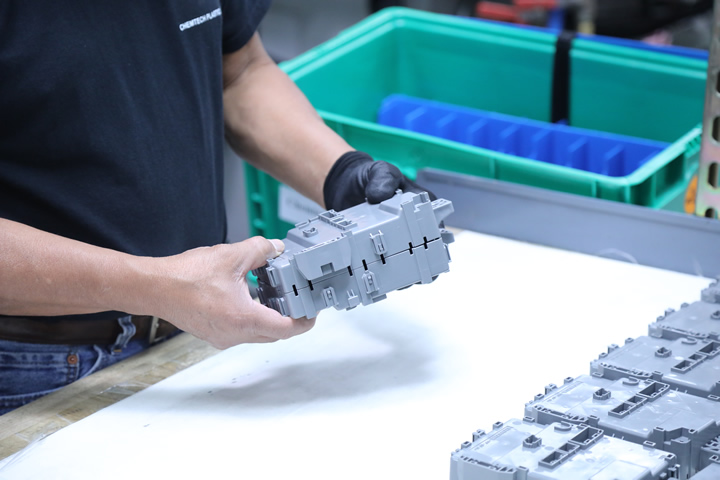
Consider an injection-molded electrical housing with a visible outer surface, internal reinforcing ribs, and a critical snap-fit feature. The customer requires a consistent cosmetic finish because the component remains visible after final assembly. During the first production run, the molding team finds sink marks above the rib intersections. The defect rate is 8%, with additional variation between cavities.
The initial response might be to raise holding pressure. That can reduce the appearance of sinks in some cases, but it is rarely the complete answer. Excessive pressure may create flash at the parting line, stress the mold, increase cycle time, or make ejection more difficult. Effective defect reduction begins by identifying why the material is shrinking unevenly and whether the mold can pack the affected area before the gate freezes.
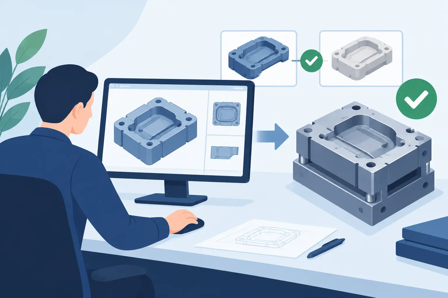
In this example, the team reviews the part design, mold construction, material condition, machine settings, and inspection results together. That matters because the visible defect may appear at the molding machine, while its underlying cause may sit in tooling geometry or part design.
Start With Evidence, Not Machine Adjustments
When defects appear, production teams are often under pressure to restore output quickly. Random parameter changes can produce a temporary improvement, but they also make it harder to identify the real cause. A controlled investigation should establish a baseline before changes are made.
For the housing, the team first records the defect location, cavity number, time of occurrence, resin lot, moisture results, cycle time, melt temperature, mold temperature, injection profile, holding pressure, and cooling time. Parts are weighed by cavity and measured at key dimensions. The weight data shows that the cavity with the deepest sink is also producing the lightest part.
That result points toward inconsistent packing rather than a purely cosmetic surface issue. The team also confirms that the defect is concentrated over thick rib-to-wall transitions. This creates a clear investigation path: material is shrinking in a locally thick section, and the cavity may not be receiving sufficient pack pressure before the gate freezes.
Find the Interaction Between Part Design and Tooling
Sink marks are often connected to wall-thickness transitions. A rib that is too thick relative to the nominal wall can hold heat longer than the surrounding surface. As the internal material cools and contracts, it pulls the outer wall inward. A machine setting may mask this condition, but it cannot fully overcome a geometry that is difficult to cool and pack.
The tool review identifies three contributing conditions. First, the ribs are close to 70% of the nominal wall thickness, where a lower ratio would reduce the risk of visible sink. Second, the gate is positioned at a distance from the affected feature, limiting effective packing. Third, the cooling circuit does not provide balanced cooling around the rib intersections.
Not every production program allows a part redesign. Existing customer approvals, assembly interfaces, and time-to-market requirements may make design changes impractical. In that case, the manufacturer must evaluate alternatives such as modifying the gate, improving cooling, adjusting steel around the feature, or changing the material grade. The right option depends on the defect severity, projected volume, tool life requirement, and cost of downtime.
Apply Corrections in a Defined Order
The team does not change every variable at once. It first verifies that the resin is dried to the supplier’s required specification and that the material feed system is stable. Moisture is not the primary cause of the sink marks, but inconsistent material condition can add variation and compromise the trial.
Next, the molding process is optimized through a structured trial. Holding pressure is increased within a safe process window, holding time is extended until part weight no longer rises, and the injection profile is adjusted to fill the cavity consistently without excessive shear. Mold temperature is balanced between core and cavity surfaces to improve appearance and stabilize cooling.
These changes reduce the sink rate from 8% to 3%, but the result is not sufficient for repeat production. The data confirms that process adjustment helps, while also confirming a tooling limitation. The team then modifies the cooling layout near the rib intersections and adjusts the gate geometry to improve packing efficiency. After the modification, the rib thickness is reduced where the design allows it without compromising structural performance.
This combined correction brings the sink-mark defect rate below 0.5% during the capability run. More importantly, part weight variation between cavities falls, confirming that the process is becoming more stable rather than merely producing better-looking samples.
Verify the Result Across a Full Production Window
A defect reduction project is not complete when a few parts look acceptable. Production conditions vary with resin lot, ambient temperature, machine warm-up, operator handoffs, and normal equipment wear. Verification must prove that the corrected process holds across the expected operating range.
For this housing, the team runs multiple cavities through an extended production trial. Inspection includes visual checks under defined lighting, part weight by cavity, critical dimension measurement, snap-fit testing, and assembly confirmation. The process window is documented with approved ranges for barrel temperatures, injection speed, changeover point, holding pressure, holding time, mold temperature, cooling time, and cushion.
The team also establishes clear reaction limits. If part weight drops outside the approved band or sink marks rise above the agreed threshold, operators know which checks to perform before production continues. This prevents the common problem of correcting defects only after a large quantity of parts has been produced.
Use Defect Data to Protect Cost and Delivery
A lower reject rate improves more than material yield. It reduces inspection time, rework, warehouse segregation, emergency shipments, and disruption at the customer’s assembly line. For procurement and operations teams, the value of a stable molding process is predictable supply and more reliable cost planning.
The most useful production data is specific enough to guide action. Track defects by type, cavity, shift, machine, material lot, and tool condition. A single overall scrap percentage can hide a cavity-specific problem or a gradual decline in cooling performance. Cavity-level data is especially valuable on multi-cavity tools because it separates process-wide variation from localized tooling issues.
Preventive mold maintenance should be part of the same control plan. Gate wear, vent blockage, cooling-channel scale, ejector wear, and parting-line damage can gradually recreate defects that were eliminated during validation. Manufacturers with in-house mold modification capability can respond faster when tooling changes are needed, avoiding the delays and communication gaps that occur when the tool and molding operation are managed separately.
When a Process Change Is Not Enough
Some defects cannot be solved responsibly through machine settings alone. Persistent warpage may require a review of gate location, fiber orientation, cooling balance, or part geometry. Flash can indicate excessive pressure, but it may also reveal a worn parting line or inadequate clamp force. Burn marks may stem from high injection speed, yet trapped air caused by insufficient venting is often the real issue.
That is why a one-stop manufacturing partner has an advantage in defect reduction. Toolmakers, process engineers, quality teams, and production operators can work from the same evidence and make decisions quickly. At Glasfil, in-house tooling, molding, quality assurance, and secondary operations support that direct feedback loop from the first trial through repeat production.
The practical lesson is straightforward: treat every recurring plastic defect as a system signal. Measure it by cavity and condition, test one controlled change at a time, and modify the part or tool when the evidence calls for it. A stable process does not depend on constant operator intervention. It gives your team the confidence to schedule production, build assemblies, and deliver finished products without waiting for the next shift to reveal a new problem.
Contact us to discuss your project, request a quotation, or arrange a technical consultation. Our team will help you determine the most cost-effective and reliable way to manufacture your part.