A part can look simple on a screen and become expensive the moment it reaches production. The top plastic molding mistakes rarely come from one dramatic failure. More often, they begin as small decisions in part design, material selection, tooling, or process setup that compound into scrap, missed launch dates, and repeated mold modifications.
For OEMs, product developers, and procurement teams, the objective is not simply to produce an acceptable part. It is to establish a stable, repeatable process that delivers dimensional consistency at the required volume and cost. That requires engineering decisions to be made with the realities of injection molding in view.
1. Treating Part Design and Mold Design as Separate Tasks
A molded component is only as manufacturable as the relationship between its geometry and its mold. One of the most costly mistakes is finalizing a part design before the tooling team has reviewed it for moldability.
Sharp internal corners, inconsistent wall thickness, insufficient draft, deep unsupported ribs, and difficult undercuts can all complicate ejection, filling, cooling, and mold construction. The part may still be possible to mold, but the required tool can become more complex, slower to cycle, and harder to maintain.
Draft is a frequent example. A vertical wall with inadequate draft may stick to the core during ejection, creating scuffing, distortion, or cycle interruptions. The solution is not always to add more draft everywhere. Cosmetic surfaces, mating requirements, texture, and assembly function all matter. The right amount depends on material shrinkage, surface finish, part depth, and the direction of pull.
Early collaboration prevents late-stage compromises. When part and mold design are developed together, the team can identify practical gate locations, parting lines, ejection points, cooling requirements, and areas that may need slides or lifters before steel is cut.
2. Ignoring Wall Thickness Transitions
Uniform wall thickness is one of the most reliable rules in injection molding, yet it is often broken for functional reasons. A designer may add a heavy boss to support a screw, thicken a local area for strength, or reinforce a wall with a large rib. These decisions can create sink marks, voids, warpage, and uneven cooling.
Thick sections cool more slowly than surrounding areas. As the material contracts, the surface may pull inward and leave a visible sink, or the interior may develop a void. Increasing packing pressure can help in some cases, but it cannot fully correct a geometry that retains heat far longer than the rest of the part.
The stronger approach is to maintain nominal wall thickness and build strength through properly proportioned ribs, gussets, and structural geometry. Transitions should be gradual rather than abrupt. This is particularly important for housings, electrical components, automotive trim, and utility parts where dimensional stability affects downstream assembly.
3. Choosing Resin by Price Instead of Performance
Resin cost matters, but material selection should begin with the part’s operating environment and functional requirements. Selecting a lower-cost polymer without evaluating impact resistance, chemical exposure, UV stability, heat performance, electrical properties, or long-term creep can shift costs from purchasing to field failures.
A bathroom accessory, for example, may require resistance to moisture and cleaning chemicals. A component used near electrical equipment may require specified flame behavior and dimensional stability. An outdoor construction part needs a different material strategy than an interior furniture component.
Material behavior during molding also matters. Filled polymers, flame-retardant grades, recycled-content materials, and engineering resins can require different processing windows, mold steel choices, gate designs, and drying procedures. Glass-filled grades may offer excellent stiffness but can increase mold wear and create directional shrinkage. A material that meets the data sheet requirements may still be a poor fit for the selected geometry or surface expectation.
The most effective decision combines performance requirements, regulatory needs, expected volume, finish, tooling implications, and supply availability. A capable molding partner can evaluate these factors before production tooling is committed.
4. Underestimating Shrinkage and Warpage
Plastic does not behave like machined metal. Every resin shrinks as it cools, and the degree of shrinkage varies by material grade, wall thickness, flow direction, packing conditions, and mold temperature. If shrinkage is treated as a simple percentage rather than a process-dependent behavior, parts can miss critical dimensions even when the mold matches the original CAD model.
Warpage is especially common in long, flat, thin-walled, or asymmetrical parts. It is driven by uneven shrinkage and nonuniform cooling. A part may be within tolerance immediately after molding, then move after it reaches room temperature or after removal from a fixture.
Tooling compensation can address predictable shrinkage, but compensation must be based on correct material data and trial results. Gate placement, cooling circuit design, rib layout, fiber orientation, and processing conditions all influence the outcome. Trying to solve warpage only by changing machine settings often leads to unstable production.
5. Building a Tool That Is Too Basic for the Production Plan
A low initial tool price can be attractive, especially when a program is under budget pressure. But a tool should be specified for its intended life, volume, part complexity, and quality requirement. A prototype tool, a low-volume bridge tool, and a high-volume production mold are not interchangeable assets.
Common problems include inadequate cooling, insufficient venting, weak ejection systems, unsuitable steel selection, and designs that make maintenance difficult. These issues may not be obvious in early sampling. They become visible when the tool runs for extended periods, cycle time increases, flash appears, dimensions drift, or unscheduled repairs disrupt supply.
The right tool is not necessarily the most expensive one. It is the one engineered for the program’s real operating conditions. For repeat production, this means evaluating cavity count, cycle-time targets, resin abrasiveness, expected maintenance intervals, automation needs, and the cost of downtime.
6. Treating Mold Flow and Sampling as Formalities
Mold flow analysis and first article sampling are decision points, not paperwork. Skipping analysis can leave the team blind to likely weld lines, air traps, pressure concerns, filling imbalance, and cooling risks. Skipping thorough sampling can allow cosmetic or dimensional defects into production before the process has been proven.
Simulation is not a replacement for physical trials. It provides direction, highlights risk areas, and improves decisions before tooling is manufactured. Sampling then confirms how the actual resin, tool, machine, and process perform together.
A strong sampling plan measures more than a few visible dimensions. It should verify critical tolerances, appearance, assembly fit, mechanical function, and repeatability across multiple cycles. Parts that pass one shot are not necessarily ready for production. The process must show that it can keep passing.
7. Adjusting Process Settings Without Finding the Root Cause
When defects appear, teams often respond by changing temperatures, pressures, cycle time, or cooling time. Process adjustment is necessary, but random adjustment can hide the actual problem and create a fragile process window.
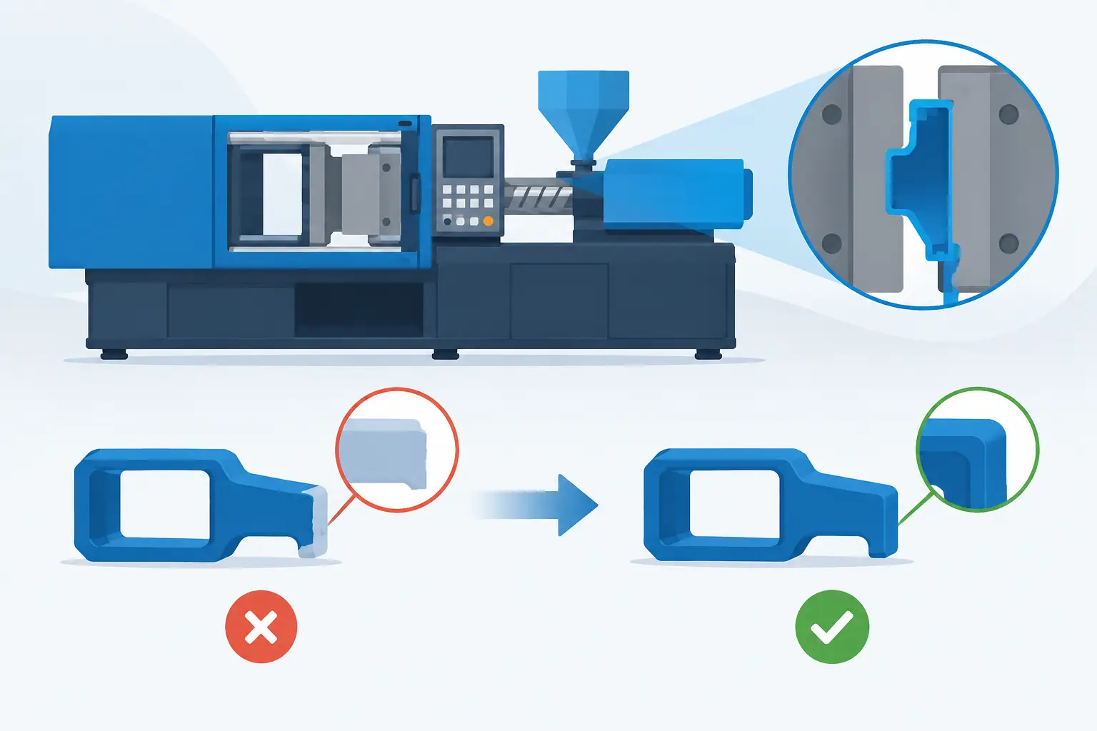
For example, flash may be related to excessive injection pressure, but it may also indicate poor clamping, mold damage, a worn parting line, inadequate venting, or a viscosity change in the resin. Short shots can result from low shot size or pressure, but they can also be caused by gate restriction, trapped air, poor melt flow, or an undersized machine capacity.
Effective troubleshooting starts by defining the defect, identifying when it occurs, checking material condition, reviewing tool condition, and comparing actual process parameters against the validated setup. Changes should be documented and controlled. This discipline reduces trial-and-error downtime and protects part consistency across shifts and production runs.
8. Leaving Quality Requirements Open to Interpretation
“Good quality” is not a usable production requirement. Without agreed standards, a supplier may inspect one feature while the customer expects another. The result is avoidable disputes, rework, and delivery delays.
Critical dimensions, cosmetic zones, acceptable surface variation, color standards, assembly tests, packaging requirements, and traceability expectations should be established before full production. Not every feature needs the same tolerance. Over-tolerancing increases tooling and inspection cost, while under-specifying critical interfaces creates assembly problems.
Quality planning should be practical. Define what must be measured, how it will be measured, the sampling frequency, and what happens when a result falls outside the agreed range. In-house quality control is most effective when it is connected to tooling, molding, finishing, and packing rather than treated as a final inspection gate.
9. Forgetting Secondary Operations and Logistics
A molded part may require printing, ultrasonic welding, assembly, metal inserts, trimming, painting, or custom packaging before it is ready to ship. Treating these steps as afterthoughts can create avoidable handling, damage, and scheduling problems.
The part design must accommodate the secondary process. Insert locations need sufficient material support. Welding surfaces need suitable geometry. Decorative finishes require protection from gate vestige, ejector marks, and handling damage. Packaging must prevent deformation and cosmetic damage during transport, especially for thin-walled or high-gloss components.
An integrated manufacturing plan reduces handoffs and gives one team accountability for how the finished product performs, not just how the raw molded part looks. Glasfil applies this approach across tooling, molding, finishing, quality checks, packing, and shipment to keep production decisions connected from the first design review onward.
Preventing Plastic Molding Mistakes Before Steel Is Cut
The most effective way to avoid the top plastic molding mistakes is to make manufacturing input part of product development, not a rescue effort after tooling begins. Review the part against its functional requirements, select resin with the end use in mind, define measurable quality criteria, and build the mold around the expected production reality.
A well-run injection molding program does not depend on last-minute parameter changes or repeated corrections. It depends on clear engineering decisions, controlled tooling, validated processes, and a manufacturing partner prepared to take responsibility for the complete path from concept to delivered part.
Contact us to discuss your project, request a quotation, or arrange a technical consultation. Our team will help you determine the most cost-effective and reliable way to manufacture your part.