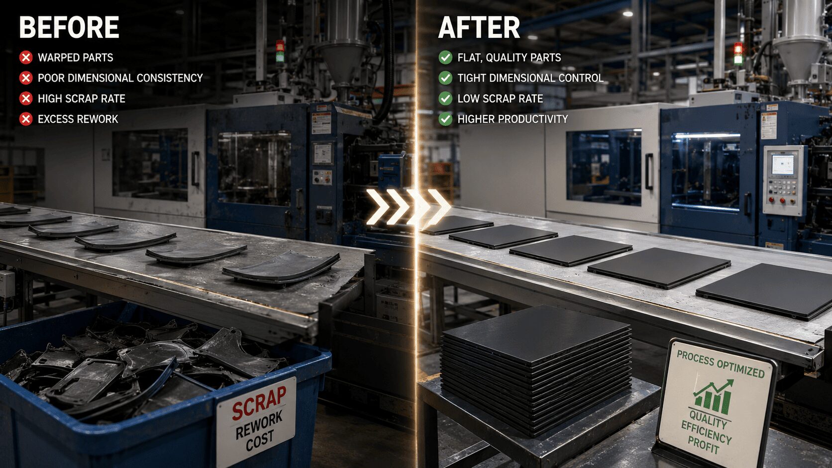
A part comes off the press looking acceptable, then shifts after cooling, inspection, or assembly. That is usually when customers ask, why do molded parts warp, and the honest answer is that warpage rarely comes from one mistake. It is typically the result of uneven shrink, stress locked into the part, or geometry that does not cool and stabilize uniformly.
In injection molding, warpage is not just a cosmetic issue. It can affect fit, sealing, flatness, fastening, and downstream automation. For OEMs and product teams, that means scrap, sorting, delayed launches, and tooling revisions that could have been avoided with better control earlier in the process.
Why do molded parts warp in injection molding?
Warp happens when one area of a molded part shrinks differently than another. All thermoplastics shrink as they cool, but they do not always shrink at the same rate in every direction. If cooling is uneven, wall thickness is inconsistent, molecular orientation is excessive, or the tool design does not support balanced filling, the part can pull out of shape.
That distortion may show up as bowing, twisting, cupping, sink-related deformation, or a gradual loss of dimensional stability after ejection. The part might pass a visual check and still fail later when it is placed into an assembly fixture. That is what makes warpage expensive. It often shows up after value has already been added.
The technical root is differential shrinkage, but the practical root can sit in the part design, resin choice, mold design, process setup, or a combination of all four.
Part design is often the first reason molded parts warp
Geometry has a direct effect on how a part cools and relaxes. Thick sections retain heat longer than thin sections, so they continue shrinking after the surrounding areas have already set. That difference creates internal stress and movement. If the part also includes long unsupported spans, broad flat surfaces, or asymmetrical features, the risk increases further.
Nominal wall consistency matters more than many teams expect. A wall transition that looks minor on a CAD screen can create a large thermal imbalance in production. Ribs, bosses, gussets, and attachment points can also pull a part if they are oversized or unevenly distributed. A common example is a housing with one reinforced corner and one open corner. Even if the cavity is machined correctly, the part may not cool symmetrically.
Flat parts are especially sensitive. Lids, covers, trays, bezels, and panel-like components tend to reveal even small imbalances. If flatness is critical, the design has to support it from the start rather than relying on process adjustment alone.
Material behavior plays a major role
Resin selection can either stabilize a part or make warpage harder to control. Semi-crystalline materials such as polypropylene, nylon, and acetal generally have higher and less uniform shrinkage than amorphous materials such as ABS or polycarbonate. That does not make them wrong choices, but it does mean the mold and process window have to account for their behavior.
Filled materials add another layer. Glass fiber can reduce overall shrinkage and improve stiffness, but it can also create directional movement. If fiber orientation becomes uneven through the flow path, one region of the part may contract differently from another. That is one reason two materials with similar datasheet values can produce very different flatness results in the same tool.
Moisture content also matters. Hygroscopic materials that are not dried correctly can process inconsistently, affecting dimensions and stability. Regrind ratio, lot variation, and colorant loading can influence shrink behavior as well. For buyers trying to solve repeated warpage, this is a useful checkpoint: if the process appears stable but the part is still moving, material consistency may be part of the problem.
Tooling design can create or prevent warpage
When customers ask why do molded parts warp, mold design is one of the first areas worth reviewing. A tool may produce parts, but that does not mean it is producing them in a balanced and repeatable way.
Gate location is critical because it influences fill pattern, packing efficiency, and molecular orientation. If the gate drives material through the part unevenly, internal stress can build into the geometry. A poor gate position can also leave one side better packed than the other, which means one side shrinks differently during cooling.
Runner balance matters in multi-cavity molds. If cavities do not fill and pack uniformly, part-to-part variation increases and warpage may show up only in certain cavities. That kind of inconsistency is difficult to sort out later unless the tool has been designed for balanced flow and measurable control.
Cooling circuit design is equally important. Uniform cooling is one of the strongest defenses against warpage, yet it is often limited by part complexity, core features, and tooling constraints. If water lines are too far from a hot section, if baffles are missing, or if one area of the cavity retains heat longer than the rest, differential shrinkage becomes more likely.
Ejection can also distort a part. A component that is still too hot or not fully stable can bend during ejection, especially if force is applied unevenly or unsupported areas are pushed too aggressively.
Processing conditions can push a stable tool into unstable output
Even with a well-designed mold, poor process control can produce warped parts. Melt temperature, mold temperature, injection speed, pack pressure, hold time, cooling time, and ejection timing all affect stress and shrinkage.
If melt temperature is too high, the material may stay mobile longer and develop more post-mold movement. If pack pressure is too low or hold time is too short, some sections may not pack out fully. If cooling time is cut to chase cycle speed, the part may leave the mold before it has stabilized enough to hold shape.
There is always a production trade-off here. Shorter cycles can improve output, but aggressive cycle reduction often raises dimensional risk. The right answer depends on the part, resin, tolerance requirements, and downstream use. A cosmetic consumer part and a functional sealing component do not have the same process priorities.
Machine consistency matters too. If screw recovery, cushion, clamp performance, or temperature control drift from shot to shot, the process may appear acceptable while dimensions slowly move out of range.
Warpage is often a stack-up problem, not a single defect
The most difficult cases are not caused by one obvious error. A part may have slightly uneven wall thickness, a resin with directional shrink, a gate location that favors one side, and a process tuned around speed instead of thermal balance. Each factor alone might be manageable. Together, they produce a part that twists or bows beyond tolerance.
That is why warpage troubleshooting should not start with trial-and-error parameter changes alone. If the root cause sits in geometry or tooling, process adjustments may only shift the symptom. You may reduce bow in one area and create sink or stress in another.
How to reduce warpage before it becomes a production problem
The best time to address warpage is before steel is cut. Mold flow analysis, shrinkage review, resin selection support, and design-for-manufacturing feedback can identify risks early, especially for large flat parts, thin-wall housings, fiber-filled materials, and parts with mixed wall sections.
After tooling begins, the focus should move to balanced filling, effective packing, and cooling uniformity. This is where in-house control becomes valuable. When tooling, molding, and quality functions are connected, it is faster to isolate whether the problem is coming from steel, resin, or setup.
In production, dimensional inspection should be tied to part stabilization conditions. Measuring a part too soon after molding can produce misleading data. Some components continue to relax after ejection, particularly in higher-shrink materials. It helps to define a consistent inspection window and validate dimensions against real assembly performance, not just immediate press-side appearance.
For existing warped parts, corrective action usually falls into three categories: process optimization, tool modification, or part redesign. Process changes are the fastest path, but they only work if enough margin exists. Tool modification can improve gate performance, venting, cooling, or ejection. Part redesign is more disruptive, but sometimes it is the only reliable fix when the geometry itself is fighting the process.
At Glasfil, this is why warpage is treated as an engineering issue, not just a molding issue. The solution often depends on controlling the full path from design refinement to tooling adjustment to repeat production.
When molded parts warp, the part is telling you something about imbalance. The fastest way forward is not guessing harder. It is tracing that imbalance back to where it started and correcting it where control is strongest.
Contact us today to discuss your project requirements or request a quotation. Let’s build a production process you can depend on.