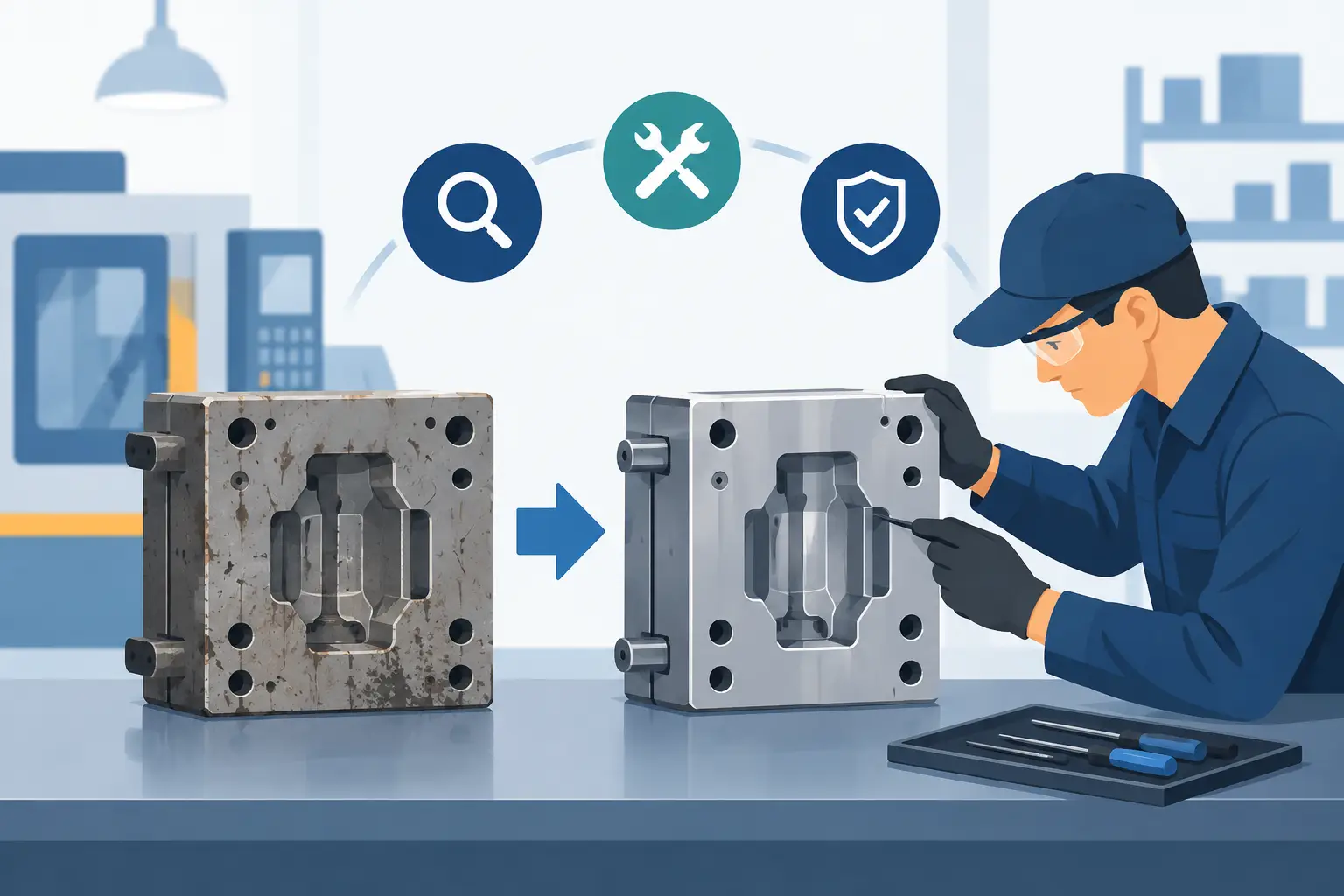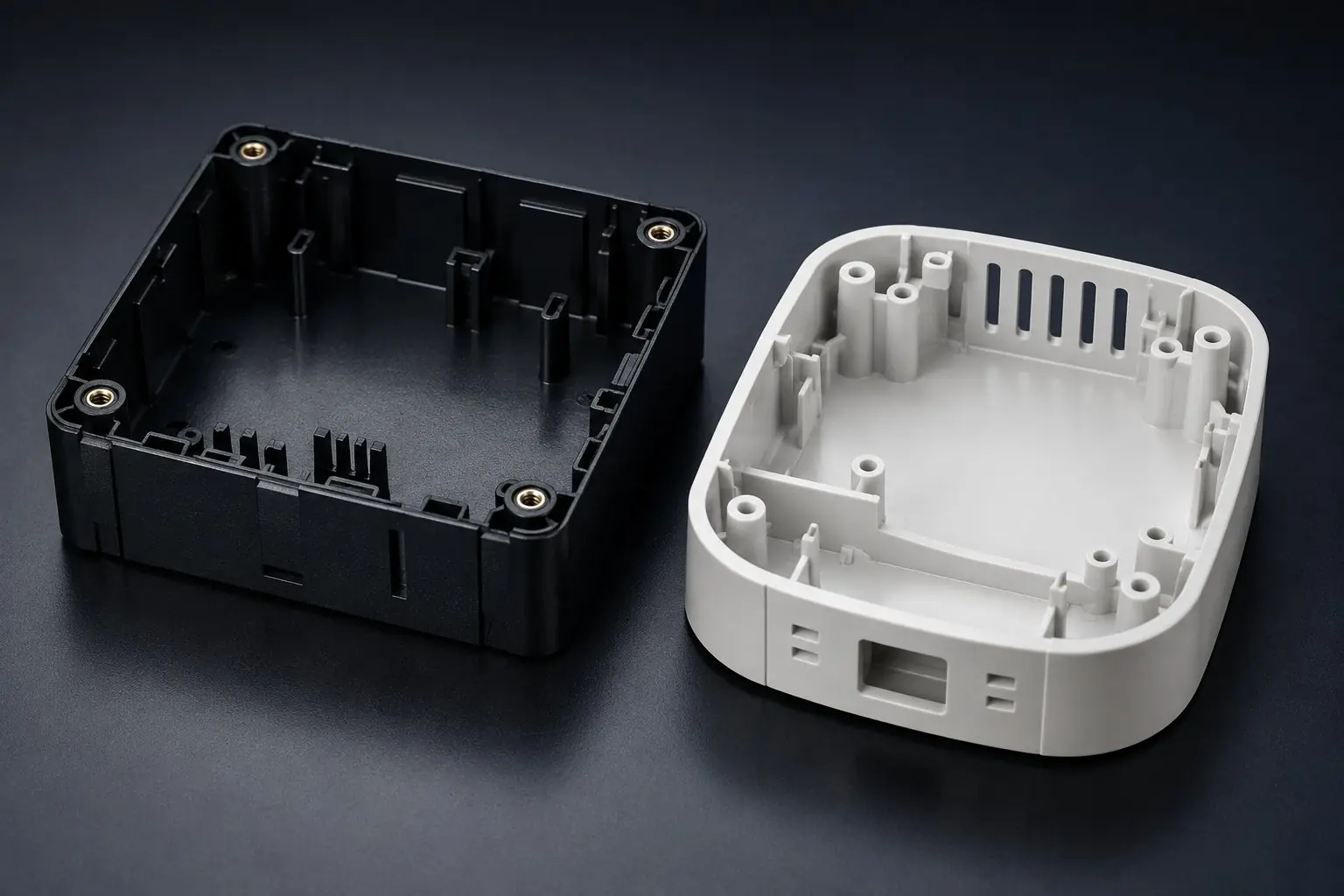
A housing rarely needs redesign because someone wants a different appearance. More often, the trigger is a cracked mounting boss, inconsistent fit with a mating assembly, water ingress, a part that warps after molding, or a tool that can no longer support reliable output. Effective plastic housing redesign starts by treating these symptoms as manufacturing and product-performance issues, not isolated cosmetic defects.
For OEMs, product developers, and procurement teams, the objective is clear: improve the part without creating new risks in tooling cost, assembly time, certification requirements, or supply continuity. That requires a redesign process that connects part geometry, resin selection, mold construction, injection molding parameters, secondary operations, and inspection from the start.
Start With the Failure, Not the CAD Model
A revised CAD file can look correct and still fail on the production floor. Before changing wall thicknesses, ribs, clips, or external surfaces, define what is wrong with the existing housing and how the problem is measured.
A housing that cracks around a screw boss may have insufficient material, but it may also be affected by assembly torque, an overly sharp transition, fiber orientation, poor weld-line placement, or a resin grade that is too brittle for the application. A warped enclosure may reflect uneven wall sections, but gate location, cooling balance, residual stress, and post-mold handling can be equally relevant. If the root cause is not separated from the visible symptom, the redesign can simply move the failure elsewhere.
The first engineering review should establish the operating conditions: load paths, mounting method, expected impact, temperature range, chemical exposure, ultraviolet exposure, ingress protection needs, electrical requirements, and target service life. It should also document manufacturing evidence from the current part, including defect patterns, reject data, assembly feedback, and tool maintenance history.
This fact base matters most when a legacy component has been discontinued or is being replicated from an existing sample. Measurements alone are not enough. The replacement part must perform in its installed condition and be practical to manufacture repeatedly.
Plastic Housing Redesign Is a System Decision
A housing is often the interface between multiple systems. It protects electronics, supports fasteners, guides cables, locates switches or displays, mates with seals, and presents the visible exterior of a product. Changing one feature can affect all of them.
Consider a redesign intended to reduce material use. Thinner nominal walls may lower part weight and cycle time, but they can increase the risk of sink marks near ribs and bosses, reduce impact resistance, and make the housing more sensitive to variation in packing pressure or cooling. The right answer may be thinner walls in some areas combined with better rib proportions, revised load paths, or a different resin rather than a universal reduction across the part.
The same trade-off applies to assembly. Snap fits can eliminate screws and speed final assembly, yet they demand careful control of material flexibility, mating tolerances, release angles, and repeated-use requirements. Threaded inserts can provide stronger, more serviceable joints, but add secondary operations and must be designed to avoid stress concentration. There is no default solution. The required production volume, service environment, assembly method, and cost target determine which option is appropriate.
A productive redesign review brings mechanical, tooling, molding, quality, and procurement considerations into one decision process. When these functions work independently, a design may be optimized for one stage and expensive at every stage that follows.
Design Geometry for Repeatable Molding
Injection molding gives manufacturers high repeatability, but only when the part is designed around the realities of molten polymer flow, cooling, shrinkage, and ejection. Housing geometry should be evaluated early for moldability, not after the visual design has been approved.
Wall thickness consistency is one of the first checks. Uniform sections promote more even cooling and reduce the likelihood of warp, voids, and visible sinks. Perfect consistency is not always possible, especially around connectors, hinges, mounting points, and reinforced corners. Where transitions are necessary, they should be gradual and supported by geometry that manages stiffness without building excessive mass.
Ribs, gussets, and bosses deserve particular attention because they are frequent sources of molding and assembly problems. A rib that is too thick can create a sink mark on the outer show surface. A boss with a sharp base can crack under fastener load. A gusset may improve stiffness while also blocking steel access or complicating ejection. These features should be considered together with the mold’s gate location, parting line, cooling channels, slide requirements, and ejector placement.
Draft angle is another practical requirement. A vertical wall may look clean in CAD, but insufficient draft can cause drag marks, deformation during ejection, or an inconsistent surface finish. Texture generally requires additional draft. Exterior styling, labeling areas, and customer-facing surfaces need to be reviewed alongside mold-release requirements before the tool is cut.
Tolerances should be applied where function demands them, not broadly across the drawing. Tight tolerances add tooling complexity, inspection burden, and production risk. Critical interfaces such as sealing grooves, connector openings, mating clips, and alignment features may need close control. Noncritical exterior dimensions often allow more flexibility. This distinction protects both part quality and piece-price stability.
Select Material Around the Application
Material selection cannot be separated from housing design. A resin that performs well in an indoor electrical enclosure may not be suitable for an automotive under-hood component, a bathroom accessory exposed to cleaners, or an outdoor utility device exposed to UV radiation and temperature cycling.
Engineers should assess mechanical strength, impact behavior, heat resistance, flame performance, chemical resistance, electrical properties, appearance, and long-term environmental exposure. ABS may support good appearance and processability for many consumer and indoor applications. Polycarbonate can offer high impact strength, while polypropylene may provide useful chemical resistance and living-hinge performance. Glass-filled materials can increase stiffness but may affect surface finish, anisotropic shrinkage, tool wear, and snap-fit behavior.
Availability and production consistency also matter. Choosing a specialized material grade can be justified when the application requires it, but it may introduce longer lead times, higher purchase cost, or regional sourcing constraints. A material decision should balance the performance requirement with the supply chain needed for repeat production.
Whenever possible, material testing should be linked to the actual failure mode. If housings have cracked after installation, evaluate assembled samples under representative torque and temperature conditions. If a product must maintain a seal, test the assembled enclosure after cycling, not only the gasket or raw plastic in isolation.
Tooling Determines How Fast a Redesign Becomes Real
A redesign does not need a completely new mold in every case. Existing tooling may be modified through inserts, cavity changes, revised cooling, or changes to moving components. The feasibility depends on the original tool construction, the scale of the geometry change, steel availability, gating, and whether revised features interfere with the existing mold architecture.
This is where in-house mold design and modification capability creates a practical advantage. The tooling team can assess the proposed housing changes against the actual mold rather than making assumptions from a part drawing alone. It may be possible to preserve valuable tool components and reduce lead time. In other cases, modifying an aging or poorly engineered tool only delays a necessary replacement. The correct decision is based on output requirements, maintenance condition, part quality, and total cost over the expected production life.
Tool design should also account for the inspection strategy. If a housing has critical sealing surfaces, clip engagement features, or tight mating dimensions, the mold and quality plan need reference points that support repeatable measurement. Quality cannot be inspected into a poorly controlled process after the fact.
Glasfil combines in-house design, mold fabrication and modification, molding, finishing, and quality control so housing revisions can be evaluated as one manufacturing program rather than handed between separate suppliers. For projects with an achievable scope and timely technical decisions, this integrated control can support completion in as little as eight weeks.
Validate the Part Beyond First Samples
First-off samples are a decision point, not the finish line. A housing can meet basic dimensions at the press and still reveal problems after assembly, transport, environmental exposure, or repeated use. Validation should reflect the conditions the product will encounter in service.
Dimensional checks should confirm critical interfaces, while functional trials verify assembly force, fastener retention, snap engagement, sealing performance, and compatibility with mating components. Visual inspection should cover gloss, texture replication, weld lines, sink marks, color consistency, and any marking or decoration requirements. When the housing supports electrical or electronic equipment, the validation plan may also need to consider flame rating, insulation distances, electromagnetic requirements, or ingress protection targets.
Production validation is equally valuable. Short runs can reveal issues that one sample does not, such as drift in part weight, variation between cavities, a difficult ejection sequence, or an unstable cycle time. The goal is not merely to prove that the part can be molded once. It is to establish a controlled process that can deliver the same functional housing across the required volume.
Make Redesign Decisions That Protect the Launch
The most effective redesigns are not the ones with the most visible changes. They are the ones that remove a known product or production risk while protecting schedule, cost, and supply reliability. That may mean retaining proven geometry, revising only high-risk features, and investing effort where it has a measurable effect on assembly or field performance.
Before approving a redesign, ask whether the revised housing has been assessed as a complete system: material, geometry, tool, molding process, secondary operations, inspection, and final assembly. When those decisions are aligned early, the result is not simply a better-looking enclosure. It is a part that can be manufactured, inspected, assembled, and supplied with confidence.
Contact us to discuss your project, request a quotation, or arrange a technical consultation. Our team will help you determine the most cost-effective and reliable way to manufacture your part.