A mold that runs 10 seconds longer than necessary may not appear to be a major problem. Across a 100,000-part production run, however, those 10 seconds can consume more than 277 machine hours. That affects unit cost, delivery dates, available capacity, and the ability to respond to urgent customer demand. Knowing how to reduce cycle time in injection molding is therefore not simply a production-floor exercise. It is a design, tooling, process, and supply-chain decision.
Cycle-time reduction must be approached carefully. A faster machine setting that creates warpage, short shots, sink marks, or dimensional variation does not improve output. The goal is to produce stable, conforming parts at the shortest repeatable cycle, with the lowest total cost.
Start With an Accurate Cycle-Time Baseline
Before changing a mold, machine setting, or material, define the current cycle accurately. Injection molding cycle time includes mold closing, injection, packing and holding, cooling, mold opening, part ejection, and any machine or operator delay between shots. Many facilities focus only on cooling time because it is often the longest portion of the cycle. In practice, lost seconds can also come from slow mold movement, extended hold pressure, inconsistent recovery, robotic handling, or manual inspection.
Use production data rather than a nominal setting sheet. Review the actual average cycle, the range between cycles, reject rate, downtime events, and part quality at different points in the run. A 32-second cycle that occasionally becomes 38 seconds is not a stable 32-second process. Variability hides capacity losses and makes delivery planning unreliable.
The baseline should also identify the limiting factor. If the part cannot be ejected without deformation, cooling is the constraint. Provided the machine waits for screw recovery, plasticizing capacity or material condition may be the issue. Assuming operators routinely pause the press to remove flash or inspect cosmetic surfaces, the root cause may be tooling wear or an overly narrow process window.
How to Reduce Cycle Time Through Part Design
Part geometry determines much of the cycle before the mold is ever built. Thick sections take longer to cool, and uneven wall thicknesses cool at different rates. This can cause sink, distortion, internal stress, and a longer hold or cooling requirement to protect dimensions.
Where product requirements allow, maintain consistent wall thickness and replace solid masses with ribs, gussets, or cored sections. Ribs should strengthen the part without creating thick intersections that trap heat. Rounded transitions also help material flow and reduce stress concentration, while appropriate draft angles support faster, more reliable ejection.
Material selection matters as well. A resin with high shrinkage, a narrow processing window, or long crystallization behavior may require a different approach than an amorphous engineering plastic. Glass-filled materials can improve stiffness and permit thinner walls in some applications, but they may increase mold wear and affect surface finish. The right decision depends on functional requirements, annual volume, appearance standards, and tooling life expectations.
Design for manufacturing reviews should happen early, particularly for automotive, electrical, utility, and consumer components with tight fit requirements. A small design revision before tool fabrication can prevent years of avoidable cycle-time cost in production.
Build Cooling Into the Tooling Strategy
For most molded parts, cooling is the largest opportunity and the largest technical risk. The part must cool sufficiently to maintain shape during ejection and handling, but cooling beyond that point only extends the cycle. Efficient cooling removes heat evenly and predictably from the areas that need it most.
Cooling-channel placement should follow part geometry rather than convenience. Channels located too far from thick sections leave hot spots and force a longer overall cooling phase. Baffles, bubblers, inserts, and targeted water circuits can improve heat removal in cores, deep features, and difficult-to-reach areas. For complex or high-volume tools, conformal cooling may provide better thermal control, although its cost must be justified by the production volume and cycle-time savings.
Water flow and temperature deserve the same attention as the tool design. Restricted lines, mineral buildup, poor circuit balancing, or unstable chiller performance can add seconds gradually until the loss becomes normalized. Measure inlet and outlet temperatures, flow rates, and pressure drop for each circuit. If one circuit is carrying significantly less flow than the others, the mold will not cool uniformly.
Mold steel selection also affects performance. High-conductivity inserts can help pull heat from localized hot areas, while durable tool steels are necessary where abrasion, pressure, or long production life demands them. There is no single best steel or cooling layout. The right system balances thermal performance, maintenance requirements, tooling cost, and expected output.
Tune the Process Without Sacrificing Quality
Process optimization should follow a disciplined sequence. Reducing cooling time first may expose an underlying packing, gate-freeze, or ejection issue. Instead, establish a capable fill stage, confirm the required pack and hold profile, verify gate freeze, then reduce cooling in controlled increments while checking part dimensions and appearance.
Gate freeze is particularly important. Holding pressure after the gate has frozen does not add useful material to the cavity. It only lengthens the cycle and may create stress in the part. A practical study measures part weight at progressively shorter hold times. When part weight stops changing, the gate is frozen. That point provides a sound starting place for setting hold time.
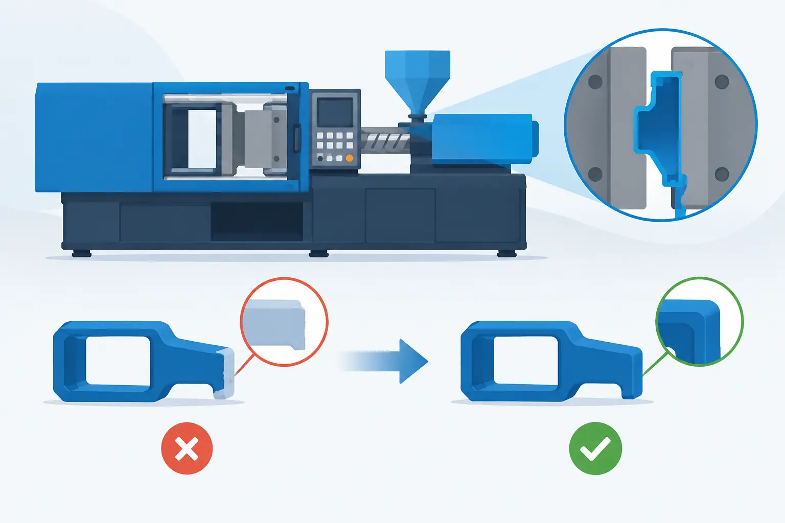
Injection speed, barrel temperature, mold temperature, back pressure, screw speed, and cushion should be treated as connected variables. Increasing injection speed may shorten fill time, for example, but it can create shear heat, burning, flash, or cosmetic defects if venting and clamp force are not adequate. Reducing mold temperature can speed cooling, but may compromise surface replication, weld-line strength, flow, or crystallization. Faster is only better when the finished part still meets specification.
Scientific molding practices help separate cause from assumption. Document the approved process window, monitor critical parameters, and use alarms or automated controls to prevent drift. A stable process often delivers more usable output than an aggressive cycle that generates inconsistent quality.
Remove Delays Outside the Cooling Phase
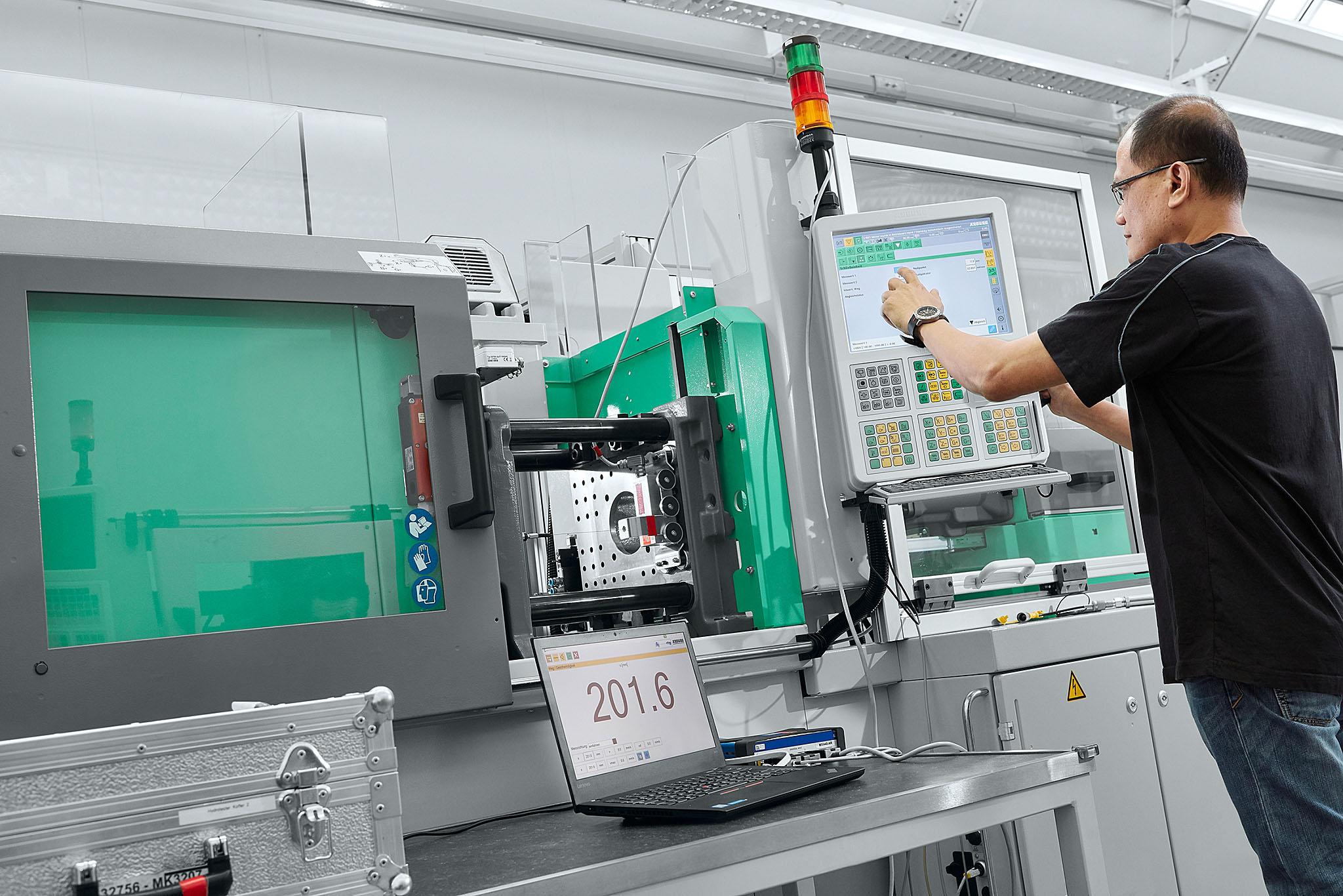
Cycle time is not only thermal. Mold opening and closing profiles, ejector travel, robot movement, conveyor timing, and operator interaction can all create unnecessary delays. On high-volume programs, even one second removed from these functions can produce a meaningful annual capacity gain.
Review dry-cycle motion separately from the molding cycle. Confirm that the mold opens only as far as necessary for safe ejection and part removal. Check whether ejector movement has excess travel, whether the robot waits for an overly conservative signal, and whether the part can be removed with a more efficient end-of-arm tool. If secondary inspection is slowing the press, consider in-line vision, poka-yoke features, or a more practical inspection plan based on critical characteristics.
Automation is most effective when the process is already stable. Adding a robot to compensate for sticking parts, inconsistent ejection, or frequent mold cleaning usually transfers the problem rather than solving it. First address the tooling and process conditions that cause interruptions.
Protect Cycle Time With Mold Maintenance
A well-designed tool can still lose performance if it is not maintained. Scale in cooling circuits, worn slides, blocked vents, damaged gates, and inadequate lubrication increase friction, create defects, and lengthen production cycles. Preventive maintenance should be scheduled based on shots, material abrasiveness, and tool complexity, not only after a failure stops production.
Track recurring issues by cavity and by tool component. If one cavity produces a slower ejection, a flash condition, or a dimensional outlier, repair it before the issue expands into a full production constraint. In-house mold modification capability is valuable because it reduces the time between identifying a problem and implementing a correction.
At Glasfil, tooling, molding, quality assurance, finishing, and delivery coordination are managed as connected operations. That level of control matters because a cycle-time improvement in one stage must not create a delay or quality problem in the next.
Measure the Result in Total Cost and Available Capacity
The best cycle-time projects do not stop at a lower number on the machine display. They measure whether the improvement increased good parts per hour, reduced scrap, protected dimensional capability, and improved on-time delivery. They also consider energy use, labor requirements, maintenance impact, and tool life.
A shorter cycle can require investment in tool modifications, upgraded cooling equipment, higher-capacity material drying, or automation. For a short-run part, that investment may not pay back. For a repeat program running hundreds of thousands or millions of parts, a few seconds can justify substantial engineering work. The business case depends on volume, machine rate, part value, customer lead-time requirements, and the risk of consuming capacity needed for other programs.
Start with measured data, then improve the constraint that limits stable output. When part design, mold cooling, process settings, machine motion, and maintenance are managed together, cycle time becomes a controllable production variable rather than an accepted cost of doing business.
Contact us to discuss your project, request a quotation, or arrange a technical consultation. Our team will help you determine the most cost-effective and reliable way to manufacture your part.