A mold that fills inconsistently rarely has a single cause. A short shot at the end of a flow path, a visible weld line, or excessive injection pressure can result from the resin, the part geometry, the gate, the venting, or the molding process itself. Knowing how to improve mold flow means treating these factors as one connected system rather than increasing pressure until the cavity fills.
For product developers and purchasing teams, this matters before production starts. Flow limitations affect tool complexity, cycle time, cosmetic quality, material selection, and long-term part cost. Addressing them during design and tool development is faster and less expensive than correcting a production tool after launch.
Start With the Actual Flow Restriction
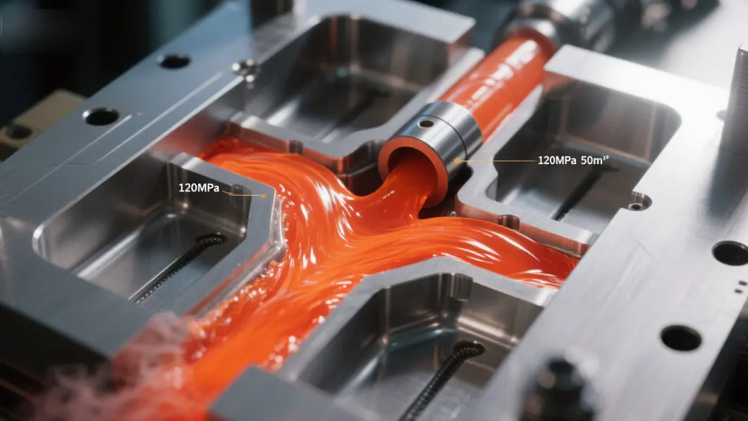
The first question is not whether the machine has enough pressure. It is where the melt loses the ability to advance. A filling study, pressure trace, and review of rejected parts can show whether resistance begins at the gate, in a thin section, around an insert, or at the final point of fill.
Short shots are the clearest signal, but they are not the only one. High injection pressure, burn marks near the end of fill, unstable part weight, hesitation marks, and weak weld lines all point to a flow imbalance. The defect location is useful evidence. If the same area fails repeatedly, the problem is usually local geometry, venting, or gate placement rather than an overall lack of machine capacity.
A disciplined diagnosis should review four areas together:
- material grade, moisture condition, and melt temperature;
- wall thickness transitions and total flow length;
- runner, gate, and vent dimensions; and
- fill speed, packing profile, and mold temperature.
Changing several variables at once may make a part fill, but it makes root-cause control difficult. Production teams should adjust one defined variable, confirm the result through part inspection and process data, then move to the next decision.
How to Improve Mold Flow Through Part Design
Part geometry determines how much resistance the molten polymer encounters before it reaches the end of the cavity. Long, thin flow paths demand more pressure and are more sensitive to normal process variation. A small change in thickness, radius, or gate location can reduce that sensitivity substantially.
Maintain practical wall thickness
Uniform wall thickness is the most reliable starting point. When melt moves from a thick section into a thin section, the thin area can freeze before the cavity is full. When it moves from thin to thick, the thick section may fill but create sink, voids, or uneven packing later in the cycle.
Uniform does not mean every feature must have the same nominal wall. Ribs, bosses, clips, and reinforced zones often require variation. The goal is to make transitions gradual. Use smooth tapers rather than abrupt steps, and avoid asking the polymer to enter a narrow section after traveling through a long, cooling path.
If a thin wall is essential for function or weight reduction, assess it against the selected resin and flow length early. A high-flow material may support the design without compromising strength, while a gate relocation or a second gate may be the better choice for a structural grade.
Remove unnecessary flow barriers
Sharp internal corners, narrow slots, deep ribs, and poorly positioned inserts interrupt the advancing melt front. They can cause hesitation, where the polymer slows in one region while another region continues to fill. The result is often a weld line, a weak area, or inconsistent surface appearance.
Generous radii improve flow and reduce stress concentration in the finished part. Ribs should be designed for structural support, not used as a substitute for a thicker wall without considering how they affect filling and packing. For parts with metal inserts, the insert location and preheating requirements should be reviewed as part of the flow analysis.
Match gate location to the part’s function
A gate should feed the thickest practical section and allow the melt to progress toward thinner or less critical areas. This supports packing and reduces the chance of premature freeze-off. The best gate position is not always the most convenient location for tool construction or automatic degating.
For appearance-sensitive components, gate placement must also account for witness marks, weld-line location, and fiber orientation. For reinforced materials, flow direction can influence warpage and mechanical performance. A gate that fills the part easily may still be unacceptable if it directs glass fibers across a snap feature or creates a visible weld line on a customer-facing surface.
Select Material for the Real Process Window
Material flow is commonly measured through melt flow rate or melt flow index, but that number is only a starting point. A higher-flow grade can reduce injection pressure and fill thin features more easily. It can also change impact strength, stiffness, shrinkage, heat resistance, chemical resistance, or long-term durability.
The right choice depends on the part’s service conditions. An electrical enclosure, automotive clip, water meter component, and bathroom fitting may all have different requirements for load, temperature, moisture, UV exposure, or approvals. Selecting a high-flow resin simply to solve a filling issue can create a more expensive issue in the field.
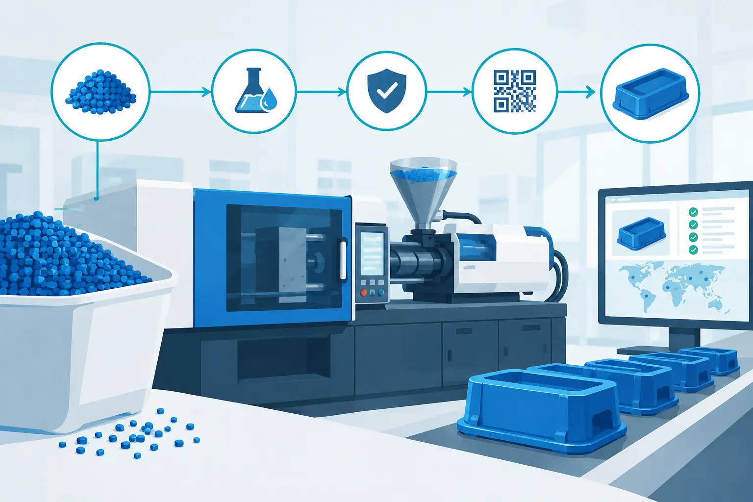
Drying is equally important for hygroscopic materials such as nylon, PET, polycarbonate, and many engineered blends. Improperly dried resin can lose molecular weight during processing, leading to splay, brittleness, unstable viscosity, and inconsistent filling. Verify the drying temperature, residence time, dew point, and material handling path rather than assuming the hopper dryer is sufficient.
Colorants, regrind, fillers, and additives also affect flow. A controlled percentage of regrind may be appropriate for some products, but excessive or inconsistent use can shift viscosity and part performance. Filled materials often need a different gate size and process profile than their unfilled equivalents.
Optimize the Tooling Before Raising Pressure
Increasing injection pressure can force a cavity to fill, but it should not be the default correction. Excess pressure raises the risk of flash, tool wear, stress, and inconsistent dimensions. Tooling changes often provide a more stable answer.
Size runners and gates for the material
Undersized runners and gates create pressure loss before the melt reaches the cavity. They can also freeze too early, limiting the ability to pack the part after filling. Gate thickness, width, and land length should be sized for the polymer, part volume, cosmetic requirements, and cycle-time target.
A larger gate can improve flow and packing, but it may leave a larger vestige or increase cooling time. Hot runner systems can reduce runner waste and support balanced filling in multi-cavity molds, yet they require accurate temperature control and disciplined maintenance. There is no universal gate style that suits every application.
Vent the end of fill
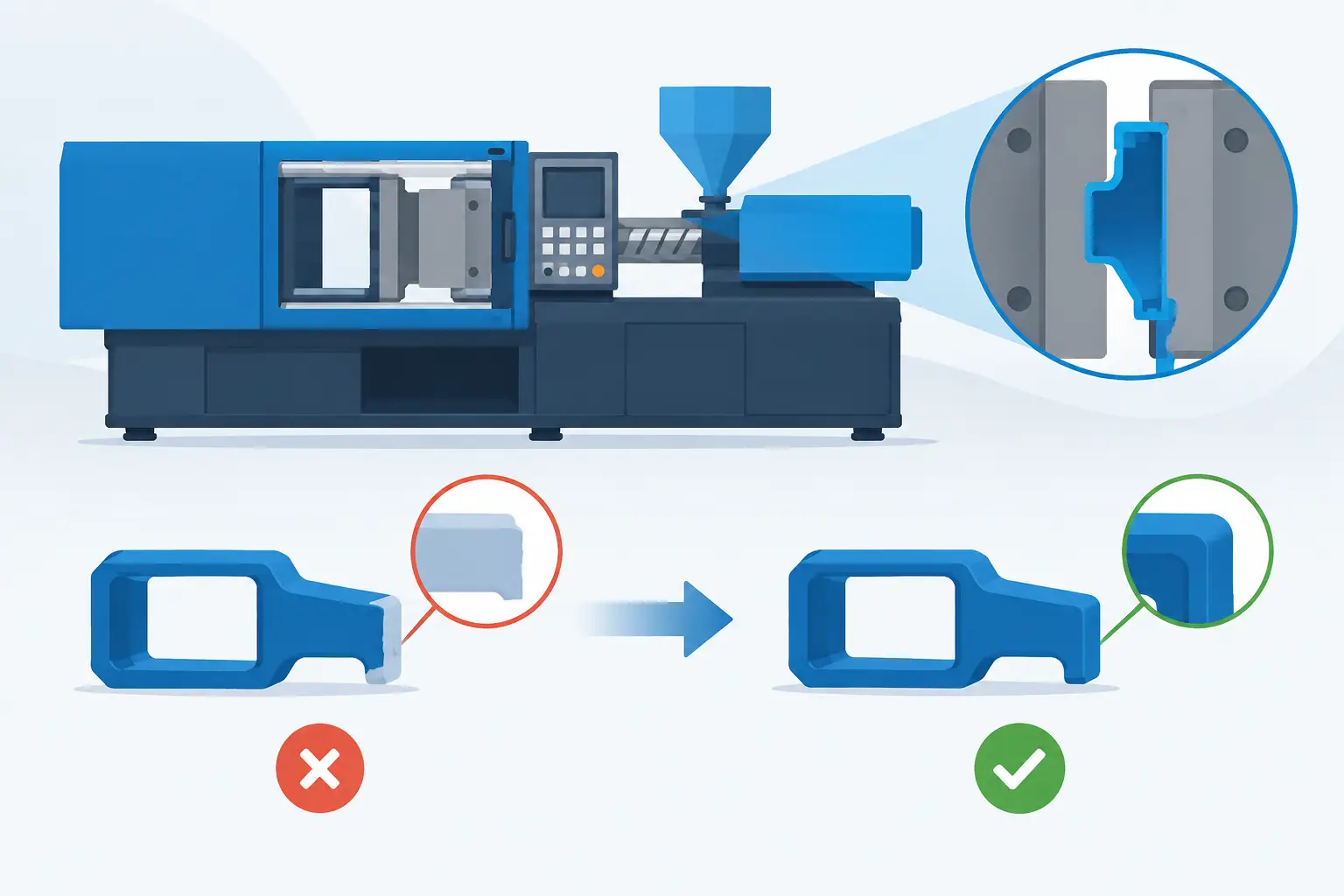
Air must leave the cavity as polymer enters. Inadequate venting causes back pressure that can look like a material-flow problem. It may also produce burn marks, diesel effect damage, incomplete fill, or variation from one cavity to another.
Vents are typically placed at end-of-fill locations, around inserts, along parting lines, and in areas where flow fronts meet. They must be deep enough to release air without allowing flash. Because vents can become blocked by residue, corrosion, or degraded material, cleaning and inspection belong in the mold maintenance plan.
Balance multi-cavity filling
A multi-cavity mold must fill each cavity consistently, not merely fill all cavities eventually. Differences in runner length, cavity temperature, vent condition, or gate dimensions can make one cavity fill first and another run short. Parts from the fastest-filling cavity may be overpacked while the slowest cavity remains underfilled.
Mold flow analysis and short-shot studies help reveal this imbalance. Corrective work may include runner adjustments, gate tuning, cavity-specific venting, cooling improvements, or process controls. At Glasfil, in-house mold design and modification capability allows tooling feedback to move directly from production data to corrective action rather than through a separate supplier chain.
Set a Stable Processing Window
Once the part and tool are capable of filling, the process must hold that performance over a full production run. The objective is not the highest possible speed or pressure. It is a repeatable process window that fills the part with enough margin to absorb normal variation in material lots, ambient conditions, and machine operation.
Start with barrel temperatures that deliver the recommended melt range without overheating the resin. Then establish mold temperatures that keep the flow front active long enough to fill detailed areas while supporting the required finish, crystallinity, and cycle time. A cold mold may create short shots or poor weld lines; a hotter mold can improve filling but lengthen cooling and reduce output.
Injection speed should be profiled when the part geometry calls for it. A faster initial fill can prevent freeze-off in a thin section, while a controlled speed near the end of fill can reduce burn marks and flash. Transfer from velocity control to pressure control should occur consistently, ideally based on screw position and confirmed by part weight or cavity-pressure data.
Packing pressure cannot compensate for an incomplete fill, but it is essential once the cavity is full. The hold profile and hold time should maintain the gate until it freezes, then stop. Holding too briefly can create sinks and low part weight. Holding too long adds cycle time without improving the part.
Validate Improvements in Production Conditions
A successful trial is not just a part that looks acceptable after a few cycles. Validate mold flow changes with dimensional checks, weight consistency, cosmetic inspection, functional testing, and process repeatability. Run enough cycles to see whether the tool reaches thermal stability, especially for thick-wall or multi-cavity components.
Document the approved process window, resin lot requirements, drying conditions, machine settings, and quality checkpoints. If a part is expected to scale from a pilot run to ongoing supply, this documentation protects the launch schedule and reduces the risk of quality drift between production batches.
The most effective flow improvement is usually a targeted combination of better geometry, correct material handling, capable tooling, and controlled processing. When those decisions are made early, the result is not merely a cavity that fills – it is a part that can be produced repeatedly at the quality, cycle time, and cost your program requires.
Contact us to discuss your project, request a quotation, or arrange a technical consultation. Our team will help you determine the most cost-effective and reliable way to manufacture your part.