A mold can be machined exactly to drawing and still fail the production requirement. It may fill inconsistently, warp after cooling, trap gas at the end of fill, or produce parts that pass a dimensional check but will not assemble on the customer’s line. Knowing how to validate mould design means proving that the tool, material, process, and part requirements will work together before costly changes become the only option.
For product developers, procurement teams, and OEM engineers, design validation is not a paperwork exercise. It is the point where assumptions are converted into evidence. The earlier that evidence is gathered, the more options exist to improve the design without delaying launch or increasing tooling cost.
Start With the Production Requirement, Not the CAD Model
Validation begins by defining what the molded part must do. A complete 3D model is necessary, but it does not establish whether a component is ready for production. The engineering team needs the operating conditions, resin specification, annual volume, cosmetic expectations, assembly interfaces, critical dimensions, and any regulatory or customer-specific requirements.
A water meter housing, for example, may need pressure integrity, stable sealing surfaces, and resistance to outdoor conditions. An electrical enclosure may require controlled wall thickness, flame-rated material behavior, and reliable fit around terminals. A decorative bathroom component may prioritize surface appearance and plating compatibility. Each requirement changes the mold design decisions that follow.
This is also where teams should separate critical-to-function dimensions from dimensions that are merely convenient to specify. Tight tolerances increase tooling and process demands. If a tolerance does not affect function, assembly, appearance, or compliance, relaxing it can improve yield and reduce inspection burden. If it is critical, the mold and quality plan must be designed to control it deliberately.
How to Validate Mould Design Through DFM Review
A design for manufacturability review is the first practical gate. It examines whether the part can be molded, ejected, cooled, and repeated at the required quality level. The review should be completed jointly by product engineering, mold design, molding process engineering, and quality personnel. Handing off the model to a toolmaker without this exchange is a common source of avoidable rework.
Check geometry that affects filling and ejection
Wall thickness should be as consistent as the part function allows. Thick-to-thin transitions can create hesitation during filling, sink marks, voids, and uneven shrinkage. Thick sections may be necessary around bosses, hinges, inserts, or load-bearing areas, but they must be treated as process risks rather than ignored as geometry details.
Draft angle is another frequent issue. A part that looks acceptable on screen can drag against cavity walls, scuff a textured surface, or stick to the wrong mold half. The required draft depends on material, texture, part depth, and expected shrinkage. Deep ribs and textured exterior surfaces usually need more draft than smooth, shallow features.
Undercuts, side holes, threads, clips, and internal details need a clear release strategy. That may involve sliders, lifters, collapsible cores, unscrewing mechanisms, or a change to the part design. There is no universal best option. A complex mechanism may preserve the product geometry but add cycle time and maintenance requirements. A geometry change may reduce tooling complexity but require customer approval. Validation makes that trade-off visible before fabrication starts.
Establish a parting-line and gate strategy
The parting line affects flash risk, appearance, venting, and mold construction. It should be placed where it supports reliable manufacturing rather than simply following the easiest split in the CAD model. For visible consumer-facing parts, the location of the parting line and gate vestige should be agreed upon early.
Gate location controls how resin enters the cavity, which influences weld lines, pressure, orientation, shrinkage, and cosmetic quality. A gate placed near a thick section can improve packing, while a poorly chosen location can leave weak weld lines at a snap feature or cause distortion across a large flat face. The validation review should assess gate type, gate size, gate removal method, and whether the location is compatible with the final use of the component.
Use Mold Flow Analysis to Test the Concept
Mold flow simulation does not replace mold trials, but it is one of the most effective ways to identify risk before steel is cut. Using the selected resin and preliminary process conditions, simulation can predict fill pattern, injection pressure, clamp force, weld-line locations, air traps, temperature distribution, cooling behavior, and likely warpage.
The value is not simply receiving a color plot. The team must interpret the result against the part’s functional requirements. A predicted weld line may be acceptable on a hidden cosmetic area, but unacceptable at a high-load clip or sealing surface. A predicted air trap may be solved with improved venting, but if it occurs in a difficult-to-machine location, changing the gate may be more practical.
Cooling deserves particular attention. Cooling channel layout directly affects cycle time, part stability, and repeatability. A mold may produce acceptable samples with a long cooling cycle, yet become commercially inefficient when production volume rises. Conversely, aggressive cooling can freeze a gate too early or create differential shrinkage. The goal is a stable process window, not just a single acceptable shot.
Simulation results should lead to decisions: revise wall thickness, adjust the gate, add vents, alter the cooling layout, change steel conditions, or confirm that the original approach is suitable. If the selected material is still uncertain, run the analysis for realistic alternatives. Material substitutions after tooling release can create problems because shrinkage, flow behavior, and processing temperature vary significantly between resin grades.
Review Tolerances, Shrinkage, and Mold Steel Conditions
Plastic parts do not leave the mold at their final dimensions in the same way machined metal components do. They shrink during cooling and can continue to condition after molding, depending on the polymer. Filled materials, crystalline resins, and parts with uneven geometry require careful shrinkage planning.
The mold designer should apply material-specific shrinkage data while allowing for the actual geometry, flow direction, gate placement, and process conditions. On parts with critical mating features, steel-safe conditions can be valuable. Leaving controlled stock on selected mould areas lets you adjust dimensions after trial results, rather than requiring welding or an insert replacement.
Tolerance validation should also consider the measurement method. A tight profile tolerance is not useful if the inspection fixture, datum scheme, or gauge repeatability has not been defined. The part drawing, mould datum strategy, assembly datums, and quality inspection plan must agree. Otherwise, different teams may be measuring the same feature from different references and reaching different conclusions.
Validate the Tool Design Before Release
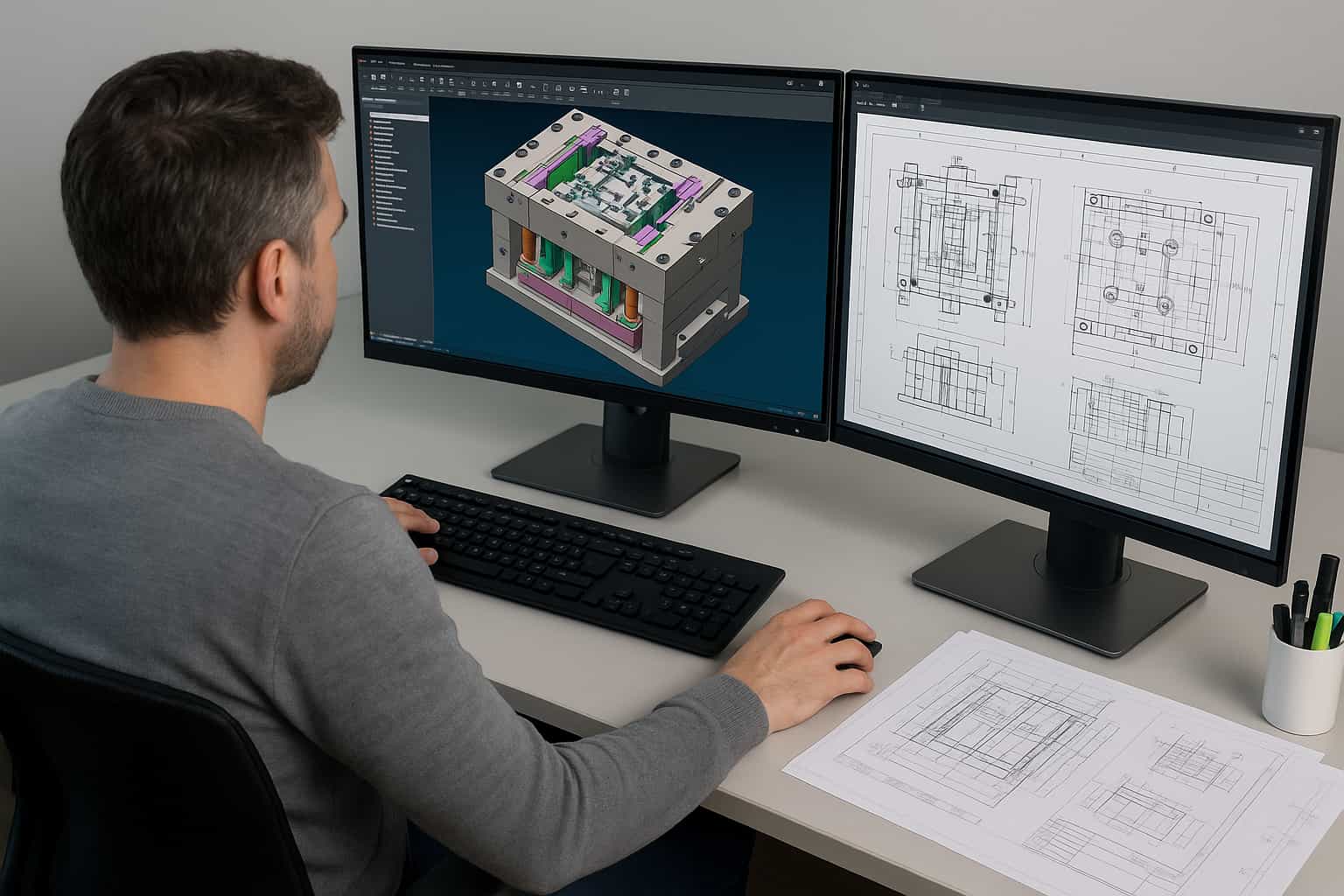
Before manufacturing begins, the mold design itself needs a formal review. This includes the cavity and core layout, runner system, cooling circuits, ejection arrangement, venting, guiding, wear surfaces, sensors, and maintenance access. A tool can be technically functional yet difficult to service, slow to troubleshoot, or vulnerable to premature wear.
A useful pre-release checklist should cover at least these areas:
- Mold base size, machine compatibility, projected area, and required clamp force
- Cavity layout, runner balance, gate design, and material flow path
- Cooling coverage, circuit identification, fittings, leak-test access, and temperature control
- Ejector placement, return system, part retention, and protection of cosmetic surfaces
- Venting at end-of-fill areas, ribs, sliders, and other locations prone to gas trapping
- Steel selection, insert strategy, wear points, and access for future maintenance or modification
Machine compatibility is especially important. The mold must suit the available press in terms of platen size, tie-bar spacing, shot capacity, nozzle interface, ejection stroke, and clamping force. A design that only works on one narrowly specified machine can limit production flexibility later. At Glasfil, in-house tooling and molding capability allows mold design decisions to be reviewed against real machine capacity before the tool enters production.
Treat T1 Samples as Evidence, Not Final Approval
The first mold trial, often called T1, is where digital predictions meet actual material behavior. The purpose is not to declare success because parts have been produced. It is to collect structured evidence on fill, pressure, temperature, cycle time, cosmetic condition, dimensional stability, ejection, and repeatability.
Trial parts should be inspected after the appropriate conditioning period, especially for materials that continue to change after molding. Critical dimensions should be measured against the agreed datums, and assembly checks should be performed with actual mating components whenever possible. A part can meet isolated dimensions while failing a real fit test due to stack-up conditions.
The trial should also establish a preliminary process window. Record the settings that produce acceptable parts, then test controlled variation in key parameters such as melt temperature, mold temperature, injection speed, pack pressure, and cooling time. If a small adjustment causes flash, short shots, warpage, or a critical dimension to move out of tolerance, the process window may be too narrow for dependable production.
Confirm Capability Before Scaling Production
A successful sample run is different from validated production. Before approval for repeat orders, confirm that the mold can run consistently at the intended cycle time and that the process can hold critical dimensions over time. This is where capability studies, first-article inspection, visual standards, and documented process parameters become valuable.
For higher-volume or regulated applications, the validation plan may include cavity-to-cavity comparison, material lot checks, traceability requirements, gauge repeatability and reproducibility studies, and defined reaction plans for nonconforming parts. The level of documentation depends on the application, but the principle remains the same: prove repeatability under normal operating conditions, not only under ideal trial conditions.
A validated mold is not frozen forever. Resin availability changes, product revisions occur, volumes grow, and wear develops in moving components. Keep the original design assumptions, flow analysis, trial results, approved samples, and modification history together. That record makes future changes faster and safer.
The best time to question a gate location, tolerance, cooling circuit, or ejection method is when the solution is still a design decision. Once production deadlines are attached to a finished tool, every correction becomes more expensive. Validate early, document what the evidence shows, and release tooling only when the mold is ready to make the part your business actually needs.
Contact us to discuss your project, request a quotation, or arrange a technical consultation. Our team will help you determine the most cost-effective and reliable way to manufacture your part.