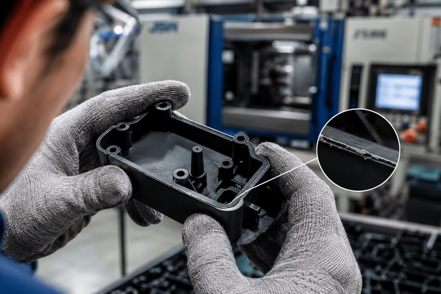
A part comes off the press looking almost right, but there is a thin ridge of excess plastic at the parting line, around an ejector pin, or near a shutoff. That small defect answers the question of what causes flash in moulding more often than most production teams would like: somewhere in the process, molten resin found a path out of the intended cavity and solidified where it should not be.
In injection moulding, flash is rarely a random event. It is usually the result of pressure, fit, wear, temperature, or material behaviour moving out of balance. For OEMs, product developers, and procurement teams, that matters because flash is not just a cosmetic issue. It adds trimming cost, increases inspection time, raises the risk of dimensional nonconformance, and can point to a larger tooling or process control problem that will only get more expensive if ignored.
What causes a flash in moulding during production
Flash occurs when plastic melt escapes between mould surfaces that are supposed to seal tightly. In a stable process, the mould halves close with enough force and accuracy to contain the melt inside the cavity. When clamp force is too low, injection pressure is too high, or mating surfaces no longer meet correctly, the material pushes into those small gaps.
That basic mechanism sounds simple, but the source can sit in several places at once. A worn mould may tolerate a process window for months, then begin flashing when summer humidity changes material condition or when a new resin lot flows more easily. A part with thin walls and long flow lengths may need higher fill pressure, which then exposes a shutoff weakness that did not appear on easier parts. This is why flash troubleshooting should not stop at the machine setting that seems most obvious.
The most common process conditions behind flash
One of the first places to look is clamp tonnage. If the machine does not generate enough clamping force to resist cavity pressure, the mould can separate slightly during fill or pack. That separation may be minimal in physical distance, but it is enough for molten plastic to enter the gap and create a flash. This is common when a mould is moved to a smaller press or when the projected area has not been evaluated correctly against actual injection pressure.
Injection pressure is another frequent driver. Higher pressure can be necessary to fill complex parts, but it also increases the force trying to open the mould. If pressure is set above what the tool and clamp system can contain, flash becomes likely. The same is true for excessive pack or hold pressure, especially on parts with gate freeze timing that is not well understood.
Melt temperature also plays a role. Hotter resin flows more easily, which can help fill difficult details, but lower viscosity makes it easier for material to enter tiny clearances at the parting line or shutoffs. Mould temperature influences this too. If tooling is hotter than intended, the melt may remain fluid longer and reach places that would normally seal off.
Overfill is another classic cause. If shot size, cushion, transfer position, or fill profile are not well controlled, the machine can push more material into the cavity than the tool can accommodate cleanly. In that case, the material looks for an exit path. The result is often flash paired with unstable part weight.
Speed can be the hidden factor. Very fast injection may create pressure spikes that are not obvious from a simple settings review. A process that appears fine on paper can still flash because the actual pressure profile at the gate or parting line is too aggressive.
Tooling problems that create flash
When teams ask what causes flash in moulding, the tooling condition is often the real answer. A mould only contains pressure as well as its sealing surfaces allow. If the parting line is worn, nicked, corroded, or contaminated, the seal can break down. Once that happens, even a process that ran cleanly before may start producing flash.
Parting line wear is especially common in long-running tools, glass-filled materials, and moulds with repeated maintenance history. Tiny damage at shutoffs, inserts, sliders, lifters, or core details can open a path for resin flow. Ejector pin clearance can do the same. Flash around pins often points to wear, poor fit, or alignment issues rather than a broad process problem.
Mould deflection should also be considered. Large tools, thin plate designs, or uneven cavity pressure distribution can cause localised opening under load. In these cases, the mould may be closing properly at rest but separating under injection pressure. The flash pattern can help identify this. If it appears consistently in one region rather than around the full perimeter, deflection or localised mismatch may be involved.
Alignment matters as much as wear. Leader pins, bushings, support pillars, and interlocks all contribute to precise shutoff. If the mould closes slightly off-centre, sealing faces may not meet evenly. That can create a flash in one area while the rest of the part still looks acceptable.
Poor venting can even contribute indirectly. When trapped gas resists the incoming melt, processors may increase pressure to force fill completion. That higher pressure may solve the short shot but trigger flash somewhere else. In other words, the visible defect is flash, but the root issue may be air management.
Material-related causes are often underestimated
Resin behaviour changes how easily flash forms. Lower-viscosity materials flow into small gaps more readily than higher-viscosity grades. If a production line switches from one resin family to another, or even between grades of the same polymer, the process window may shift enough to expose flashing.
Moisture conditions can alter flow characteristics, especially in hygroscopic materials. Improper drying may not always cause flash directly, but it can change melt behaviour and part consistency. Regrind ratio can also matter. Depending on the material and application, too much regrind may affect viscosity in ways that make process control less stable.
Additives and fillers change the picture as well. Glass-filled materials can accelerate tool wear, increasing the mechanical risk of flash over time. Lubricated or highly flowing compounds may seal less forgivingly at shutoffs. This is why material selection should be evaluated alongside tooling design, not after defects appear in production.
How to diagnose flash without chasing symptoms
Effective troubleshooting starts with the flash location. Flash at the parting line usually points toward clamp force, pressure, mould wear, or mismatch. Flash around ejector pins suggests pin fit or wear. Flash at inserts, slides, or shutoffs often indicates local damage, alignment loss, or deflection.
From there, the right move is controlled isolation. Reducing injection pressure, pack pressure, or melt temperature can reveal whether the problem is process-driven. If flash remains even as pressure comes down and fill becomes incomplete, the tool may already have a sealing issue. If small process changes remove the flash immediately, the mould may still be serviceable but running outside a safe window.
Part weight data helps. A flashing process often shows unstable weights or drift between cycles. Clamp force monitoring, cavity pressure if available, and dimensional checks at the flash zone all add useful evidence. The goal is not just to remove the defect for one shift. The goal is to identify whether the root cause sits in machine capability, tool condition, material behaviour, or a combination of those factors.
Preventing flash requires tool and process control together
The most reliable way to prevent flash is to design and run the project with enough control margin. That starts at the tooling stage with proper shutoff design, adequate support, sound venting, and a realistic assessment of projected area and required clamp tonnage. It continues with disciplined process development so fill pressure, transfer position, hold profile, and temperature settings stay within a stable range.
Maintenance is not optional here. A mould that produces acceptable parts today may be moving toward flash if sealing faces are wearing or if alignment components are losing precision. Regular inspection of parting lines, vents, pins, inserts, and support elements reduces the risk of sudden quality loss during a production run.
This is also where integrated manufacturing support has real value. When mould design, mould repair, process setup, and quality assurance operate under one roof, teams can respond faster and more accurately. A supplier like Glasfil can evaluate whether the issue calls for a process adjustment, a tooling correction, or both, instead of pushing the problem downstream.
Flash is a small defect with large implications. It tells you that pressure is escaping control somewhere in the system. Treat it as an engineering signal, not just a trimming problem, and you protect cycle time, part quality, and delivery performance before a minor edge becomes a major production setback.
Ready to move from design to dependable production? Work with a partner that combines tooling control, process engineering, and manufacturing under one roof.
Contact us today to request a quote or schedule a discussion with our technical team.