A plastic part can look straightforward on a screen and still become expensive, inconsistent, or impossible to produce at volume. The difference is usually decided before the first production cycle. This plastic molding process guide explains how B2B product teams move from a part requirement to repeatable, quality-controlled injection molded components.
For OEMs, engineers, and procurement teams, injection molding is not simply a manufacturing step. It is a chain of engineering decisions involving part geometry, resin behavior, tool construction, machine capacity, quality criteria, and delivery planning. Control the chain early, and production becomes faster and more predictable. Leave decisions disconnected, and cost appears later as tool changes, cosmetic defects, delayed approvals, or unstable cycle times.
Plastic Molding Process Guide: From Design to Delivery
Injection molding begins with a product requirement, not a mold. Before tool design starts, the manufacturer needs to understand what the part must do in service, how many units are required, where it will be used, and which characteristics are critical. A water meter component, electrical enclosure, automotive clip, and bathroom accessory may all be molded plastic parts, but they demand very different material, tolerance, surface, and validation decisions.
A practical project brief defines the part function, annual volume, target launch date, environmental exposure, assembly interfaces, color requirements, appearance standard, and inspection needs. It should also identify whether the component is new, replacing a discontinued part, or improving an existing design. This information gives the engineering team a basis for selecting the right production route rather than treating every part as a standard molding job.
1. Part design and manufacturability review
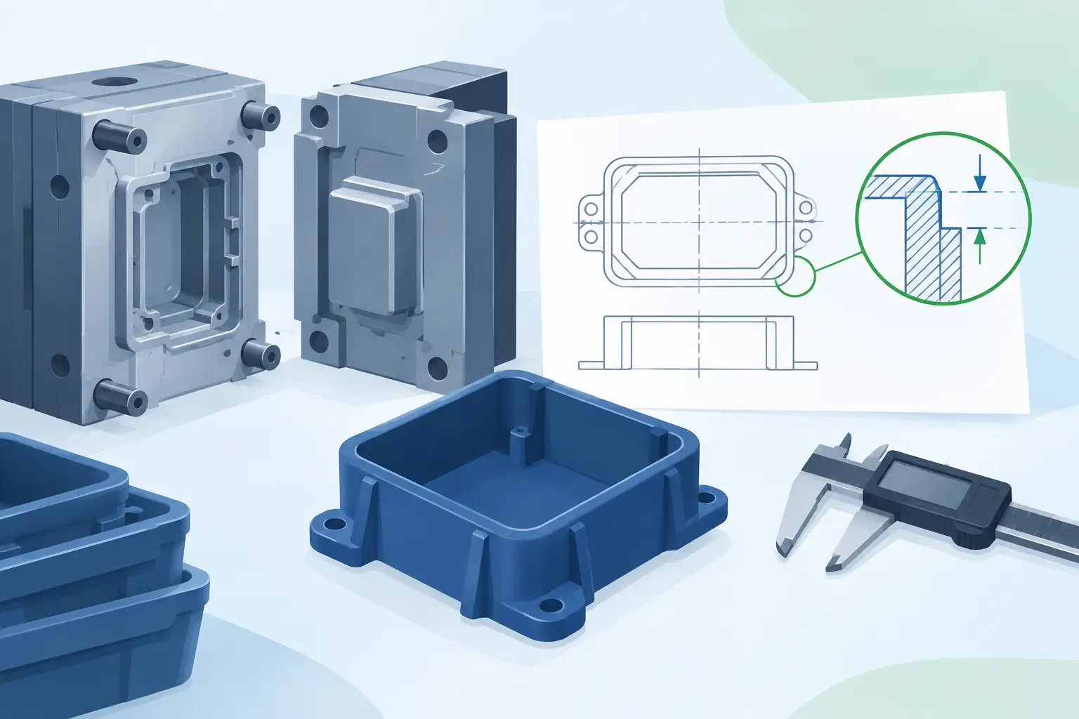
The first technical checkpoint is design for manufacturability. A CAD model may meet the product concept but still require refinement before molding. Common concerns include uneven wall thickness, insufficient draft, sharp internal corners, deep ribs, inaccessible undercuts, and tolerances that do not reflect resin shrinkage.
Wall thickness deserves particular attention. Thick sections cool more slowly than thin ones, increasing the risk of sink marks, voids, warpage, and long cycle times. A more uniform wall structure generally produces a more stable part. Where stiffness is required, ribs and gussets are often more effective than adding bulk, provided their dimensions are designed to avoid visible sinks on cosmetic surfaces.
Draft angle is another frequent source of avoidable difficulty. Parts must release from the mold reliably, especially when they have textured surfaces or deep walls. The correct draft depends on the material, texture, depth, and geometry. There is no single number that works for every project. A component with a polished surface may release with less draft than a heavily textured housing, but relying on the minimum can create unnecessary production risk.
Undercuts are not automatically a problem. They may require slides, lifters, collapsible cores, or manual operations, all of which affect tooling complexity and cycle time. The right decision depends on production volume and functional value. For a high-volume program, a more advanced tool mechanism can be justified. For a limited run, redesigning the feature may deliver a better cost outcome.
2. Material selection based on service conditions
Choosing resin by appearance or unit price alone is a costly shortcut. The selected material must perform after molding, assembly, shipping, and years of use in the final environment. Mechanical load, temperature range, chemical exposure, UV exposure, electrical requirements, impact resistance, dimensional stability, and regulatory needs all matter.
Polypropylene may suit chemical-resistant utility products and living hinges. ABS can provide a good balance of impact performance and surface appearance for housings. Polycarbonate offers strength and clarity but requires careful processing. Nylon can deliver excellent mechanical properties, although moisture absorption must be considered when defining dimensions and end-use performance. Glass-filled materials increase stiffness but can affect tool wear, surface finish, flow behavior, and warpage.
Material selection also changes mold design and molding parameters. Resins shrink at different rates, flow differently through thin sections, and respond differently to cooling. A supplier with engineering and tooling capability in-house can use these characteristics during design rather than discovering them after a tool has been built.
3. Mold design and fabrication
The mold is the production asset that converts a resin into a repeatable component. Its quality determines far more than the shape of the part. Mold design influences cycle time, dimensional consistency, surface finish, maintenance frequency, automation potential, and long-term cost per part.
A well-engineered mold design addresses the cavity layout, gate location, runner system, cooling channels, ejection method, venting, steel selection, and expected molding machine. Gate placement affects how resin fills the cavity and where weld lines, flow marks, or stress may occur. Cooling must be balanced to reduce cycle time without creating distortion or uneven shrinkage. Venting is essential because trapped air can cause burns, incomplete filling, or poor surface quality.
Tool cavitation should match forecast demand and business priorities. A single-cavity mold may reduce upfront investment and simplify early validation. A multi-cavity tool can lower unit cost at higher volumes but requires tighter balance and greater initial commitment. This is a commercial as well as technical decision. The lowest tool price is not always the lowest total manufacturing cost.
In-house mold fabrication and modification reduce handoffs between designers, toolmakers, and molding operators. At Glasfil, this integrated control supports faster iteration when test results show that a gate, cooling circuit, ejection detail, or critical dimension needs adjustment.
4. Trial molding and process validation
Once the mold is complete, the project enters trial molding. Initial samples are used to confirm that the part fills, packs, cools, ejects, and meets the agreed requirements. This stage is not simply about producing a sample that looks acceptable. It is about establishing a stable process window that can be repeated in production.
Operators and engineers evaluate mold temperature, melt temperature, injection speed, holding pressure, cooling time, clamp force, and cycle time. They inspect for short shots, flash, sinks, warpage, burn marks, weld lines, splay, and color variation. Dimensional checks confirm whether shrinkage and deformation align with the design assumptions.
A good validation approach distinguishes between cosmetic acceptance and functional acceptance. A minor flow line might be acceptable inside an industrial assembly but unacceptable on the front face of a consumer product. Likewise, a dimension may look within tolerance when measured immediately after molding but shift after conditioning. Requirements should reflect real product performance, not just a drawing review.
5. Production molding and quality control
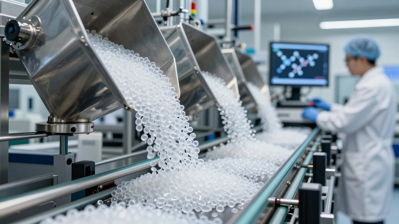
After approval, production begins with defined process parameters, material handling rules, inspection plans, and packaging standards. Resin preparation is essential. Hygroscopic materials such as nylon, polycarbonate, and ABS can absorb moisture from the air. If they are not dried correctly, surface defects and weakened properties can result.
Machine selection must also fit the tool and part. Clamp force, shot size, injection capacity, mold dimensions, and automation requirements influence the choice. Using a machine that is too small can create flash or unstable molding conditions. Using one that is excessively large can reduce efficiency and control. A manufacturer with a range of machine capacities can match each program to the appropriate equipment rather than forcing every tool into the same production setup.
Quality assurance should be built into production, not treated as a final sorting activity. First-off inspection, in-process measurement, visual standards, sampling frequency, traceability, and documented corrective action all contribute to dependable output. For critical assemblies, additional checks may include leak testing, fit checks, torque testing, color verification, or functional testing.
Secondary Operations Are Part of the Process
Many molded parts are not complete when they leave the press. They may need trimming, assembly, ultrasonic welding, insert installation, printing, painting, plating, labeling, or custom packing. These operations should be considered during part and mold design because they can affect datum selection, handling features, cosmetic surfaces, and production flow.
For example, a metal insert can be molded in or installed afterward. Insert molding may improve retention and reduce downstream assembly, but it adds tooling and process complexity. Post-mold insertion may be more flexible for lower volumes or multiple product variants. The right choice depends on the component’s load requirements, annual demand, and total cost of ownership.
Packaging also deserves early attention. A precisely molded part can still arrive damaged, scratched, mixed, or contaminated if packing is not designed for its geometry and transport route. Buyers should define pack quantity, protection level, labeling, and shipment requirements before final approval.
What Controls Cost, Lead Time, and Risk
The main cost drivers are not limited to resin price and press time. Tool complexity, number of cavities, surface finish, tolerance demands, secondary operations, quality documentation, and packaging all affect the final commercial model. Tight tolerances can be necessary, but applying them to every dimension adds expense without always adding value. Identify the dimensions that control fit and function, then assign practical tolerances to the rest.
Lead time is similarly shaped by early decisions. Clear CAD data, defined acceptance criteria, realistic material selection, and prompt sample feedback prevent delays. Frequent late-stage design changes, unclear ownership of approvals, and disconnected tooling and molding suppliers usually extend the schedule. An integrated manufacturing partner can shorten the loop because design refinement, tool changes, trial runs, finishing, and packing are managed within one coordinated operation.
The best time to solve a molding issue is while it is still a digital decision or a tool design discussion. Bring the molder into the project before the drawing is frozen, define what the part must achieve in the field, and make approval criteria measurable. That approach gives your team a part that is not only moldable, but ready to perform, scale, and ship with confidence.
Contact us to discuss your project, request a quotation, or arrange a technical consultation. Our team will help you determine the most cost-effective and reliable way to manufacture your part.