A production efficiency improvement example is only useful if it translates into actions on the factory floor. For an injection-molded part, that means more than increasing machine output. It means producing conforming parts at a predictable cycle time, with less scrap, fewer interruptions, and no compromise in tool life or customer specifications.
Consider a common situation: an OEM needs to increase supply of a plastic housing used in an electrical assembly. The part is technically sound, but production is falling behind plan. Operators are stopping the press to address short shots and flash, inspection is rejecting too many parts, and the cycle time has gradually increased. The apparent answer may be to run the machine faster. In practice, that can create more rejects and make the actual output problem worse.
The right response is to identify where time and quality are being lost, then correct the source of variation. This is how an integrated molding manufacturer turns a production issue into measurable capacity.
Production Efficiency Improvement Example in Injection Molding
In this representative example, a customer requires 120,000 molded housings per month. The tool is running on a 250-ton press, using a four-cavity mold and a filled engineering-grade resin. The planned cycle time is 42 seconds, but actual cycles average 49 seconds once minor stoppages and quality interventions are included. Scrap is 6.5%, primarily from flash near the parting line and incomplete filling in one cavity.
The business impact is larger than the scrap rate suggests. Every rejected part consumes resin, machine time, energy, inspection time, and handling. Every unscheduled stop disrupts labor planning and creates a risk that shipments will miss the required delivery window. Adding overtime or another machine may temporarily protect supply, but it does not fix the process.
The improvement target is not simply “more pieces per hour.” It is to restore a stable 42-second cycle, reduce scrap below 2%, and maintain dimensional and cosmetic requirements throughout the run. That target increases good-part output without adding cavities, purchasing a new mold, or accepting lower standards.
Step 1: Separate the Losses Before Changing the Process
A production team first records what is happening during the run. Cycle time is divided into mold-close, fill, pack and hold, cooling, mold-open, ejection, and part handling. Stops are categorized rather than logged as a general machine delay. Quality rejects are traced by cavity, shift, material batch, and defect type.
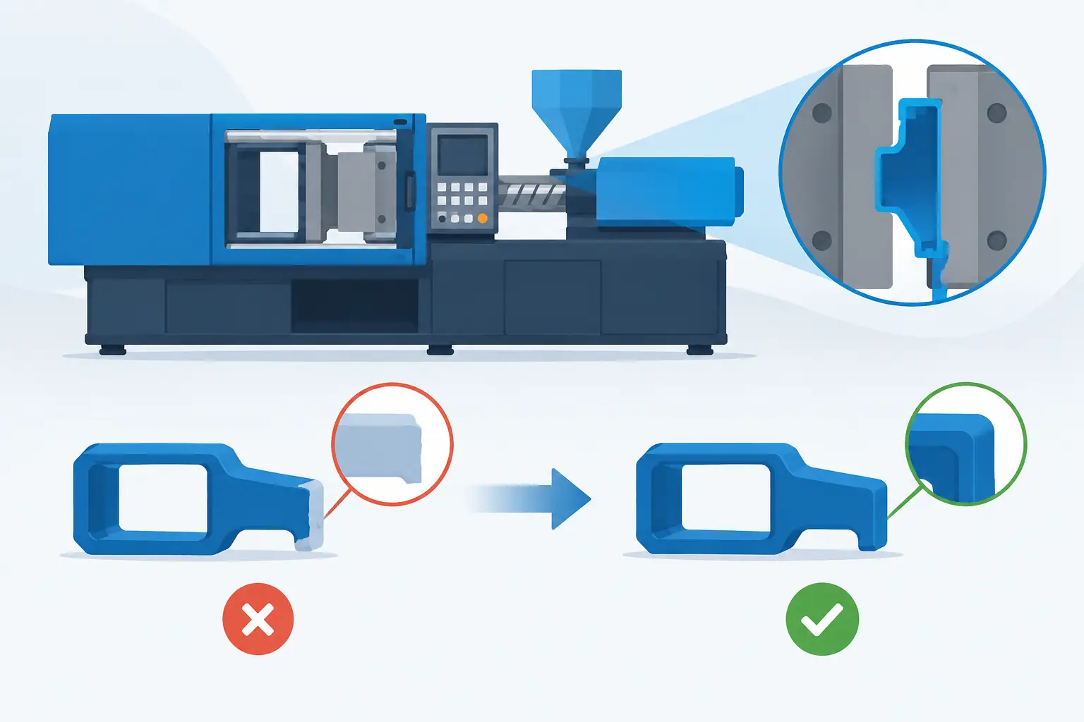
This level of detail matters because similar symptoms can have different causes. Flash may result from a worn parting surface, excessive injection pressure, poor clamp force selection, or contamination preventing full mold closure. A short shot may point to material moisture, restricted flow, inconsistent melt temperature, venting problems, or an unstable transfer point. Adjusting pressure without evidence may hide one issue while creating another.
In this case, the data shows that cavity three produces most short shots, while flash is concentrated after extended runs. The cooling phase has also been increased by operators to prevent deformation during ejection. These findings point toward a combined tooling and process-control issue, not an operator-speed issue.
Step 2: Correct the Tooling Condition at the Source
The mold is inspected in-house. The team finds wear along a section of the parting line, restricted venting close to cavity three, and uneven cooling performance caused by mineral buildup in one cooling circuit. None of these issues alone is unusual. Together, they force the process outside its stable window.
The repair plan includes restoring the affected parting surface, cleaning and validating vents, flushing the cooling channels, and confirming water flow and temperature balance across the tool. The mold is then tested before returning to production. Because design, tool modification, and molding operations are under one roof, corrections can be evaluated against real production conditions instead of being passed between separate suppliers.
Tool maintenance is often treated as downtime to be minimized. That is the wrong calculation when a degrading tool creates recurring scrap and unpredictable stops. Planned intervention is usually less expensive than running a mold until defects, damaged components, or missed deliveries force an emergency repair.
Step 3: Establish a Repeatable Process Window
Once the tool is restored, the molding parameters are reset through a structured trial. The team verifies resin drying conditions, barrel temperatures, injection speed profile, transfer position, holding pressure, hold time, cooling time, clamp force, and mold temperature. The goal is not to find the fastest possible setting for a short trial. It is to define a process window that produces good parts consistently.
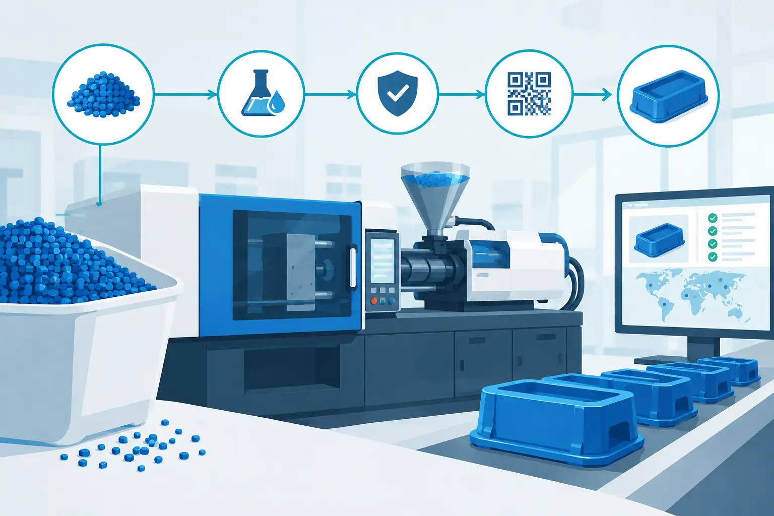
For this housing, the improved venting allows the cavity to fill at a more controlled injection profile. Balanced cooling removes the need for the extra cooling time that operators had added as protection against warpage. Material preparation is standardized so resin moisture does not introduce avoidable variation from one shift to the next.
The validated setting sheet becomes a production control document. It identifies target values, approved ranges, startup checks, and escalation points. This gives operators clear guidance while still allowing engineering to respond when the process moves outside normal behavior.
Step 4: Move Quality Checks Closer to the Process
Final inspection alone cannot protect production efficiency. It identifies defects after material and machine time have already been consumed. In-process verification catches drift earlier, when correction is faster and the quantity at risk is smaller.
For this program, first-off approval is completed at startup and after any significant interruption. Operators check critical dimensions with defined gauges, review the cosmetic surface around the parting line, and confirm part weight within the established tolerance. Quality records are linked to cavity identification, making it possible to see whether a defect is random or tied to a specific area of the mold.
This approach does add discipline to the production routine. However, the small amount of time spent on controlled checks is far less costly than discovering several hours of nonconforming output at the end of a shift. The best inspection plan is not the most intensive one. It is the one that detects meaningful change early enough to act.
The Measurable Result of the Improvement
After the tooling corrections and process validation, the average cycle time returns to 42 seconds. Scrap falls from 6.5% to 1.8%, and minor stops associated with quality adjustments decline sharply. On the same four-cavity mold and the same press, good-part output rises by roughly 20% over the previous actual production rate.
That result is more valuable than a headline output number. The customer gains better delivery confidence, lower resin loss, more predictable labor requirements, and less pressure to invest in emergency capacity. The manufacturer gains a stable program that can be scheduled accurately and repeated across future orders.
The exact result will depend on the part geometry, polymer, mold condition, cavity count, volume requirement, and customer tolerances. A high-gloss consumer component may need a different balance between cycle time and surface quality than a reinforced industrial housing. Similarly, a low-volume service part may justify a different level of automation than a program running millions of units annually. Efficiency is not one setting. It is the best controlled balance for the product and production objective.
What Buyers Should Ask Before Approving an Improvement Plan
When a supplier proposes an efficiency improvement, ask how losses will be measured, whether the mold can be inspected and modified in-house, and how quality will be verified during the run. Ask for the expected change in good-part output, not just a proposed reduction in nominal cycle time. A shorter cycle is not a gain if rejection rates rise or tool maintenance becomes more frequent.
It is also useful to ask who owns the interaction between mold design, processing, quality, and secondary operations. Fragmented responsibility slows corrective action. A full-service partner can evaluate the part, tool, process, finishing requirements, packing, and shipment plan as one production system. At Glasfil, that control supports faster decisions from design refinement through repeat production.
The strongest production gains often come from disciplined fundamentals: a healthy tool, stable material preparation, validated parameters, and quality data that reaches the people running the machine. When those fundamentals are managed together, increased output becomes a controlled manufacturing result rather than a risky push for speed.
Contact us to discuss your project, request a quotation, or arrange a technical consultation. Our team will help you determine the most cost-effective and reliable way to manufacture your part.