A tolerance callout can determine whether a plastic part assembles cleanly for years or creates a costly production problem before the first shipment. For product developers and procurement teams, knowing how to specify part tolerances means translating functional requirements into dimensions that tooling, molding, inspection, and production can reliably achieve.
The goal is not to make every dimension as precise as possible. The goal is to control the dimensions that affect fit, function, safety, appearance, and downstream assembly, while allowing reasonable variation everywhere else. That distinction protects part performance and avoids unnecessary tooling complexity, cycle-time pressure, and inspection cost.
Start With Function, Not a Tighter Number
Every tolerance should answer a practical question: What happens if this feature varies? A bore may locate a mating pin. A sealing surface may prevent leakage. A snap-fit arm may need a controlled wall thickness to deliver the right retention force. A visible gap between two exterior panels may affect perceived product quality even when the assembly still functions.
Before assigning a tolerance, identify the feature’s job in the finished product. Then define the allowable condition at each limit. If a shaft must enter a hole, calculate clearance using the largest shaft and smallest hole. If a clip must hold a cover in place, review the full stack-up of the clip, cover, mating edge, and material flexibility. If two housings must sit flush, consider the accumulated variation across all locating features rather than treating each dimension in isolation.
This functional approach prevents a common error: copying a tolerance from a CAD model, legacy drawing, or metal component without considering how injection-molded plastic behaves. A dimension that is easy to hold in machined aluminum may be unnecessarily expensive, or even unstable, in a molded polymer.
How to Specify Part Tolerances by Feature Type
Not all dimensions deserve the same control. A practical drawing separates critical features from general geometry.
Critical-to-function features usually include mating interfaces, locating datums, threaded inserts, bearing seats, sealing lands, connector interfaces, and snap-fit geometry. These features need explicit tolerances because their variation directly affects performance or assembly.
Critical-to-appearance features may include visible gaps, shutoff lines, texture boundaries, logos, and surfaces that join with another visible component. Their tolerance strategy may involve both dimensional control and agreed cosmetic acceptance criteria.
Noncritical dimensions should generally use a sensible general tolerance rather than individual tight callouts. Overall length, hidden ribs, internal clearance areas, and non-mating wall features often have room to vary without changing the product’s performance. Over-dimensioning these areas creates more inspection work without improving the part.
For molded components, control should also reflect the feature itself. A hole formed by a core pin can be controlled differently from a hole created by a secondary drilling operation. A dimension near the gate may behave differently from one at the end of fill. A long, unsupported flat wall is more likely to warp than a compact, ribbed feature.
Build the Tolerance Stack-Up Before Tooling Starts
Parts do not function alone. They function as assemblies. A well-toleranced part can still fail if the stack-up across multiple components has not been analyzed.
Start by establishing datums that match the way the part is located in the real assembly. The primary datum should stabilize the part in the most meaningful orientation. Secondary and tertiary datums should locate it consistently without over-constraining the design. These references become the basis for controlling holes, slots, edges, and other mating features.
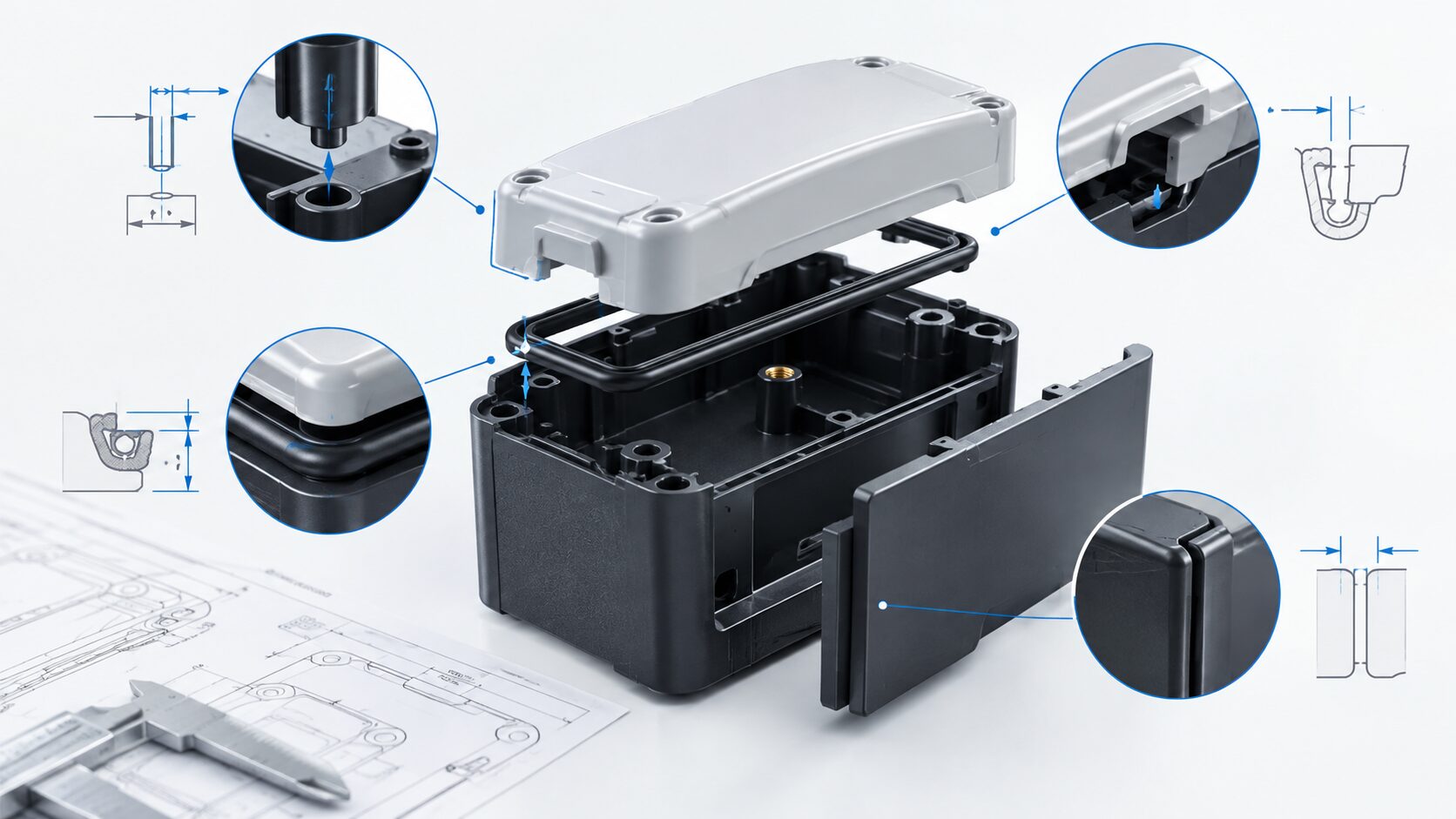
Then review worst-case conditions. For a simple cover-and-base assembly, evaluate the smallest possible clearance and the largest possible visible gap. For a water-handling component, check the worst combination of sealing diameter, groove dimensions, O-ring variation, and material shrinkage. For an electrical enclosure, assess connector alignment, screw boss location, and cover engagement together.
Statistical stack-up can be appropriate for high-volume assemblies with stable, capable processes. However, worst-case analysis remains valuable when a failure cannot be accepted, when parts are sourced from multiple production lots, or when interchangeability is mandatory. The right method depends on product risk, production volume, and the consequences of a field failure.
Account for Material Shrinkage and Part Geometry
Injection molding produces repeatable parts, but plastic does not behave like a fixed block of material. It flows, cools, shrinks, and can continue to condition after molding. Material selection, wall thickness, mold temperature, packing pressure, gate location, fiber content, and part geometry all influence final dimensions.
Semi-crystalline materials often show higher and more directional shrinkage than amorphous materials. Glass-filled polymers can offer higher stiffness and lower shrinkage in some directions, yet the fiber orientation can make dimensional behavior anisotropic. Hygroscopic materials may change dimensions after absorbing moisture. If the part operates in heat, humidity, chemicals, or under load, the specified tolerance should reflect the service environment, not only the measurement taken at the molding machine.
Wall thickness changes matter as well. Thick sections cool more slowly and are more prone to differential shrinkage, sink, and warpage. Long parts, broad flat panels, and asymmetric designs can move as internal stresses relax. In these cases, a tight overall flatness or profile requirement may cost far more than redesigning the geometry with consistent walls, ribs, gussets, or improved part location.
A capable molding partner should review these risks before the tool is finalized. At Glasfil, in-house mold design, mold modification, molding, and quality control allow dimensional feedback to move quickly between engineering and production rather than becoming a slow supplier handoff.
Use GD&T When It Solves an Assembly Problem
Geometric dimensioning and tolerancing is valuable when size dimensions alone cannot clearly communicate the requirement. Position tolerance can control a hole pattern relative to functional datums. Profile tolerance can control a complex molded surface. Flatness, perpendicularity, and concentricity-related controls may be necessary where sealing, alignment, or assembly location depends on geometry.
GD&T should clarify inspection and function, not decorate a drawing. For example, applying a tight profile tolerance to an entire molded housing can force unnecessary control of freeform areas that have no functional role. It is often more effective to control the specific interface surfaces, mounting points, and connector locations while giving nonfunctional exterior surfaces reasonable freedom.
Use datum schemes that can be inspected repeatably. If a quality technician cannot fixture the part in a way that represents assembly conditions, the requirement may be difficult to verify and difficult to enforce. Agree early on whether inspection will use gauges, calipers, pin gauges, a coordinate measuring machine, optical measurement, or functional fixtures.
Define the Measurement Condition
A tolerance is incomplete if the measurement conditions are unclear. Plastic dimensions can vary based on part temperature, conditioning time, moisture content, and the timing of inspection after molding. A dimension recorded immediately after ejection may differ from the dimension measured after the part has stabilized.
Specify when the part should be measured, especially for engineered materials or tight interfaces. Define the measurement temperature when needed, the datum setup, the gauge method, and any functional test conditions. For a sealing component, a go/no-go functional gauge may offer more meaningful assurance than a long list of individual dimensions.
This is also where realistic capability matters. A supplier can produce a first article that meets an aggressive tolerance through sorting, slow cycles, or intensive adjustment. The more relevant question is whether the dimension can be held consistently across normal production, multiple cavities, material lots, and repeat orders. Production tolerances should be based on demonstrated process capability, not a one-time sample result.
Avoid Costly Over-Specification
Tight tolerances are not free. They can require more precise tooling, additional mold actions, more controlled processing, longer stabilization, secondary machining, higher scrap risk, and expanded inspection. They may also limit cavity count or complicate future mold maintenance.
The most effective drawings concentrate cost where it creates value. If a feature only needs to clear another part by 0.080 inch, a tolerance of +/- 0.002 inch may offer no benefit. If a snap fit has a narrow functional window, tighter control may be justified, but the design should first be reviewed for material selection, draft, wall thickness, and assembly force.
A useful engineering review asks five questions:
- Which dimensions affect fit, sealing, movement, strength, safety, or appearance?
- Which datums represent the actual assembly condition?
- How will material shrinkage, warpage, and conditioning affect the feature?
- Can the feature be inspected consistently in production?
- Is the required tolerance achievable at the intended volume and cost?
The answers often lead to a better result than simply tightening every number on the drawing.
Treat Tolerancing as a Manufacturing Decision
The best tolerance specification is created through collaboration between product design, tooling engineering, quality, and production. Design intent must remain clear, but the route to achieving it should account for mold construction, polymer behavior, machine capability, cavity layout, and inspection planning.
Request a manufacturability review before releasing tooling. Share mating parts, assembly conditions, cosmetic expectations, expected volumes, and known failure modes. If a feature is truly critical, make that priority visible in the drawing and inspection plan. If it is negotiable, say so early enough for the tooling strategy to reflect it.
A well-specified tolerance does more than control a dimension. It gives the manufacturer a clear target, gives quality teams a repeatable verification method, and gives your product a better chance of assembling correctly at full production scale. Start with the function the customer will experience, then let the drawing reflect the realities of molded plastic production.
Contact us to discuss your project, request a quotation, or arrange a technical consultation. Our team will help you determine the most cost-effective and reliable way to manufacture your part.