A plastic component that binds, wears prematurely, or shifts under load can stop an automated cell just as effectively as a failed sensor. That is why automation equipment plastic parts must be engineered around their real operating conditions, not simply moulded to match a drawing. Material selection, dimensional control, surface finish, and production consistency all affect machine uptime.
For OEMs, machine builders, and industrial product teams, the right part is rarely the lowest-cost part at the quote stage. It is the part that maintains its function across thousands or millions of cycles, installs predictably, and can be reproduced without creating new variation from one production run to the next.
Where Plastic Parts Earn Their Place in Automation
Automation equipment uses plastic components for far more than cosmetic covers. Common applications include sensor housings, cable-management components, grippers, guide rails, spacers, rollers, belt supports, control-panel elements, enclosures, fluid-handling parts, protective guards, and custom fixtures. In the right location, injection-moulded plastic can reduce assembly weight, eliminate corrosion concerns, improve electrical insulation, and consolidate several machined or fabricated components into one part.
The key qualification is “in the right location.” A part carrying a static load has different requirements from a sliding guide, a pneumatic fitting, or a housing next to a heat source. Designers should define how the component works before selecting a resin or approving a mould design.
A conveyor guide, for example, may need low friction and strong wear resistance. A safety guard may prioritise impact performance, visibility, and chemical resistance. A connector housing may require electrical insulation, flame performance, and close control around mating features. Treating all three as generic plastic parts creates risk before tooling even begins.
Start With the Operating Environment
The most useful part specification begins with service conditions. Temperature range, chemical exposure, UV exposure, humidity, cleaning agents, impact risk, vibration, and expected cycle count should be documented early. So should the mating materials. A polymer that performs well against aluminium may behave differently against stainless steel, coated steel, or another polymer.
Load data matters just as much. Engineers should distinguish between a one-time load, a repeated load, and a continuous load. Plastics can creep under sustained stress, particularly at elevated temperatures. A bracket that passes an initial fit check may gradually deform in service if wall thickness, ribbing, material choice, and mounting geometry have not been considered together.
Tolerance requirements also need context. Not every dimension needs tight control, but the dimensions that govern alignment, sealing, snap engagement, gear mesh, or sensor positioning do. Applying unnecessarily tight tolerances across an entire part raises tooling and inspection cost. Leaving critical interfaces undefined produces the opposite problem: a part that is inexpensive to mould but inconsistent in assembly.
Material Selection Is a Performance Decision
Commodity materials such as polypropylene, polyethene, ABS, and polystyrene can be appropriate for low-load housings, covers, and packaging-related equipment. Engineering polymers are often a better fit where strength, heat resistance, wear resistance, or dimensional stability are central to function.
Nylon is frequently used for mechanical components because of its strength and wear characteristics, although moisture absorption can affect dimensions and properties. Acetal can be effective for low-friction moving components and precision mechanisms. Polycarbonate offers impact resistance, while glass-filled grades can improve stiffness where a part must resist deflection. High-temperature or chemically demanding applications may call for specialised materials, but their processing window and tooling requirements must be evaluated before committing to production.
There is no universal “best” resin for automation equipment plastic parts. A glass-filled material may improve stiffness but can increase tool wear, alter surface appearance, and make snap features less forgiving. A low-friction resin may reduce sliding resistance while offering lower structural strength. The right choice depends on the component’s job, expected life, production volume, and the cost of failure on the machine floor.
Design for Moulding Before Cutting Steel
Injection moulding rewards design discipline. Uniform wall thickness helps parts fill, cool, and shrink more predictably. Sharp internal corners concentrate stress, while appropriate radii improve material flow and long-term durability. Ribs can add stiffness without making the whole component excessively thick, but poorly proportioned ribs may create sink marks or distortion.
Draft angle is another practical requirement. Parts must release from the mould reliably without scuffing functional surfaces or creating unnecessary cycle delays. This is especially relevant for deep housings, textured surfaces, and components with internal features. When draft is ignored during early design, the correction can require geometry changes that affect adjacent components and assembly tooling.
Undercuts, threads, inserts, living hinges, and snap fits are all achievable in moulded parts, but each changes mould complexity and production economics. A moulded thread may be the right solution for a high-volume assembly. For lower volumes or critical fastening points, a metal insert or secondary operation may provide better durability. The decision should be based on function and total cost, not on a preference for the fewest possible manufacturing steps.
Tooling Control Determines Repeatability
A high-performing design can still fail in production when tooling is poorly engineered or difficult to modify. Moulds must account for resin shrinkage, gate location, cooling, ejection, venting, and the surfaces that control critical dimensions. These details influence cycle time, cosmetic quality, warpage, and consistency from cavity to cavity.
For automation components, tooling flexibility is valuable because early production often reveals practical improvements. A guide rail may need a modified mounting feature. A housing may require more clearance around a connector. A fixture component may need a different identification mark or a strengthened rib. When mould design, fabrication, modification, and moulding are controlled in one operation, changes can be evaluated and implemented without unnecessary handoffs.
Glasfil supports this integrated approach with in-house mould design, fabrication, modification, moulding, finishing, and quality control. With 19 machines up to 560 tons across two manufacturing plants, the company can match tooling and moulding capacity to parts ranging from compact precision components to larger industrial housings.
Secondary Operations Are Part of the Part
Many automation components do not leave the moulding machine ready for installation. They may need threaded inserts, ultrasonic welding, pad printing, laser marking, assembly, trimming, drilling, or packaging designed for line-side use. These operations should be considered during design and quoting, rather than treated as an afterthought.
For example, a moulded enclosure may need a metal insert to withstand repeated service access. A control component may require permanent markings that remain legible after cleaning. A multi-part assembly may need poka-yoke features that prevent incorrect orientation during final assembly. Integrating these needs into the manufacturing plan reduces handling, shortens lead times, and makes accountability clearer.
Packaging also deserves attention. Precision parts can be damaged by loose bulk packing, while assembled components may need cavity trays or labelled kits to protect orientation and simplify downstream installation. The best packaging method depends on part geometry, surface sensitivity, shipment distance, and how the customer receives material on the production floor.
Build Quality Around Critical Features
Quality assurance should reflect the actual risks of the application. A cosmetic cover may need visual inspection and colour control. A sensor bracket may require dimensional checks on mounting holes and alignment surfaces. A fluid-related component may need leak testing. Measuring every dimension on every part is rarely practical, but ignoring the dimensions that control function is equally costly.
A practical quality plan identifies critical-to-function features, defines inspection methods, establishes sampling or control frequency, and records the results needed for traceability. First-article approval is especially useful when a part includes multiple interfaces, tight tolerances, or secondary operations. It gives engineering, procurement, and production teams a shared physical reference before volume production begins.
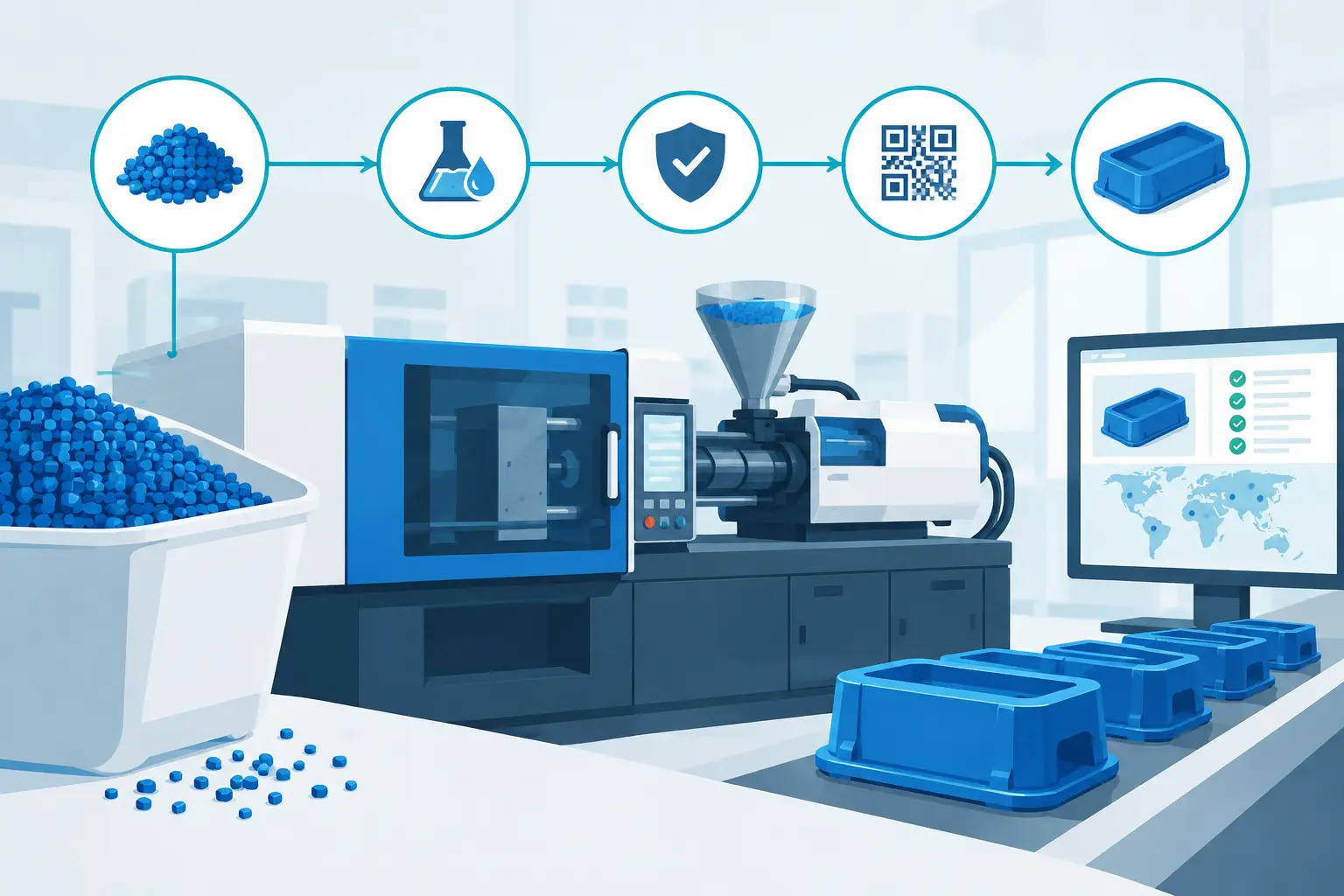
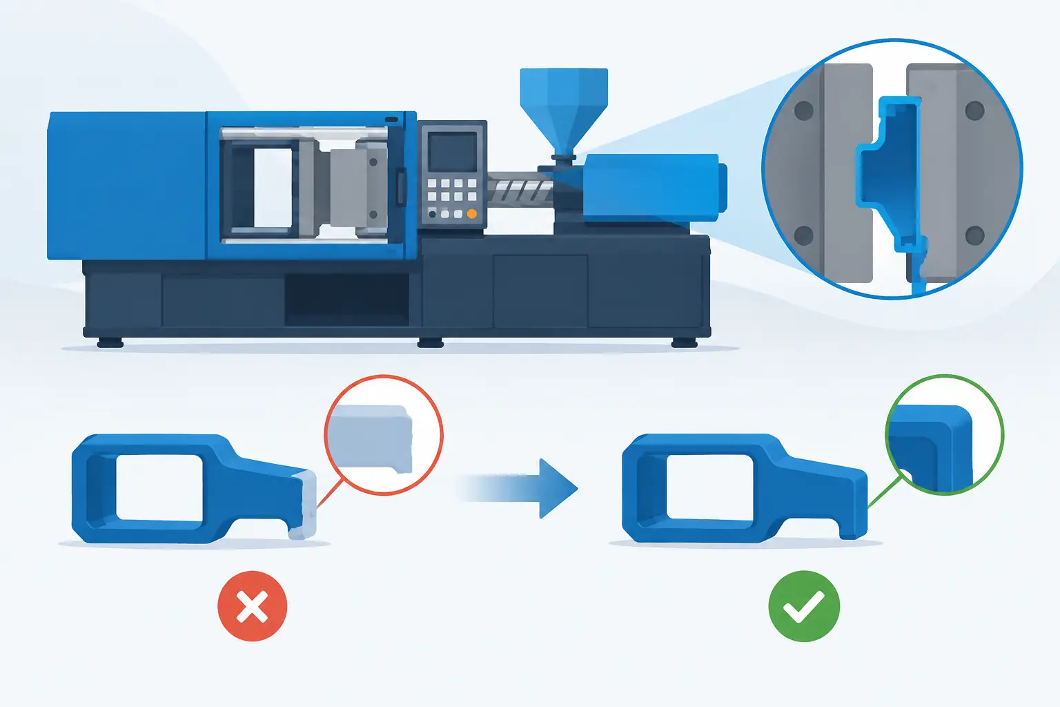
Repeat orders should not be treated as routine by default. Material batches, process settings, tooling condition, and packaging requirements must remain controlled. Moulds also require preventative maintenance to avoid flash, wear, poor ejection, and dimensional drift that can gradually affect assembly performance.
Choose a Manufacturing Partner for the Full Production Reality
The best supplier relationship begins before a purchase order is released. A capable moulding partner can review part geometry, identify manufacturing risks, recommend material options, and explain where a design change will reduce cost or improve reliability. That is particularly valuable when a company is moving from prototype to repeat production, replacing an obsolete component, or correcting field issues in an existing machine.
Speed matters, but speed without engineering control often transfers problems downstream. The stronger approach is to compress development through coordinated design review, tooling execution, moulding trials, quality validation, and secondary processing. For projects with clear requirements, an integrated manufacturer can move from concept to finished production parts in a focused timeline, including an eight-week completion target where project scope allows.
When automation equipment plastic parts are specified around the machine’s real loads, environment, interfaces, and production needs, they become a dependable part of the system rather than an overlooked source of downtime. The most productive next step is to review the component before tooling begins, while changes are still fast, affordable, and fully within engineering control.
If you are evaluating a new project or facing ongoing tooling and production challenges, contact us to discuss your requirements, request a technical consultation, or submit your RFQ.